The physical appearance of the ANC depends
on the type and mission of the aircraft. Figure
8-14 shows two different types of ANC. View A
of figure 8-14 shows an ANC that consists of an
equipment rack and seven amplifier modules,
which are listed below.
1.
Roll servo amplifier
2.
Pitch servo amplifier
3.
Yaw servo amplifier
4.
Roll computer amplifier
5.
Pitch computer amplifier
6.
Heading computer amplifier
7.
Command coupler
Each of the seven modules contains sub-
assemblies and sub-subassemblies. Some of these
are interchangeable between modules. The roll,
pitch, and yaw servo amplifiers are identical.
The other modules have individual differences.
The computer, through an interlocking relay
arrangement in conjunction with the control panel
mode selection switches, controls signal switching
operations. A calibration board on the front of
the ANC provides gain adjustments of the major
system parameters.
View B of figure 8-14 shows a one-channel
amplifier/computer. Normally, this particular
type of autopilot computer consists of three
individual amplifier/computer modules--one for
each control surface--aileron channel (roll),
rudder channel (yaw), elevator channel (pitch).
This one-channel computer accomplishes
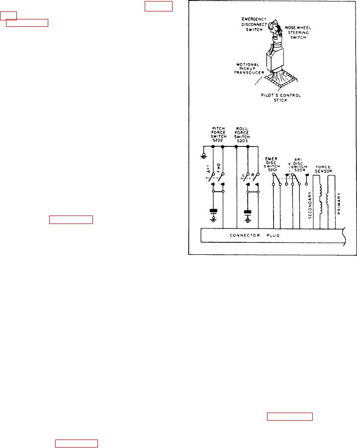
Figure 8-15.-Control stick steering components.
analog computations by using servomechanisms.
These servomechanisms consist of electro-
attitude of the aircraft through regular stick
mechanical computer cards and electronic
control. When the pilot releases stick pressure, the
amplifier cards mounted in the amplifier/
computer. In addition, a transformer board and
force switch opens, allowing the AFCS to
reengage roll. If the bank angle is above a given
a resistor board provide summing networks. The
networks combine the various signals supplied to
angle (for example, 5 degrees), the AFCS will
maintain the bank angle. If the bank angle is
and generated within the unit. An interlocking
below the given angle, the AFCS automatically
relay arrangement is included to perform most of
the switching control in the automatic flight
returns to wings level.
The pitch force switches close when a fore
control system.
or aft pressure is on the control stick. This
momentarily disengages the AFCS. The stick
CONTROL STICK. --Control stick or control
wheel steering is used on some aircraft to control
pressure also couples a signal through the E
the aircraft electronically through the AFCS,
pickoff transformer that is labeled "force
using the regular control stick or control wheel.
sensor," as shown in figure 8-15. The signal
On fighters, the signals are generated in a unit
couples with the AFCS pitch channel. Depending
such as the one labeled "motional pickup
on the direction of the stick pressure (fore or aft),
transducer, " in figure 8-15.
the aircraft either climbs or dives.
When the AFCS is on and the control stick
Electrical/Electronic Sensors
is moved left or right, pressure on the roll force
Many electrical and electronic sensors provide
switch momentarily disengages the roll channel
input to the AFCS. This section of the TRAMAN
of the AFCS. The pilot then controls the roll

