COMPASS INFORMATION. --Normally,
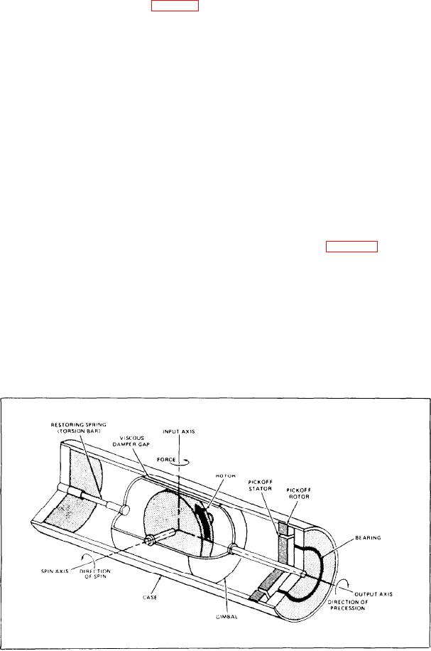
Internally, each rate gyro consists of a small
viscous-damped, single-degree-of-freedom gyro
compass information for the AFCS is supplied by
the aircraft compass system or the inertial
with a differential transformer pickoff (fig. 8-20).
navigation system (INS). However, some compass
The gyroscopic element of each gyro is the rotor
information is developed for the AFCS.
of a synchronous motor. The rotor mounts in a
The compass system/INS incorporates a gear
gimbal frame and spins at high speed about its
train to drive several synchros. The gear train is
spin axis. The gimbal is flexible and free to rotate
driven by a motor generator unit that aligns to
about an output axis. This axis is perpendicular
aircraft heading. Of the several synchros, one
to both the spin axis and the input axis. A
provides heading information to the pilot's compass
torsion-restoring spring that couples the gimbal
indicator. One synchro attached to the gear train
to the case limits the rotational freedom about the
through a clutch provides a clutched heading.
output axis. The gyro gimbal carries the pickoff
When the AFCS is not engaged, the clutch
rotor on an extension along its output axis. The
remains de-energized, wit h its rotor spring loaded
p i c k o f f rotor senses the relative angular
to an electrical null condition. When the pilot
displacement of the gimbal and case.
With the pickoff rotor in its zero or neutral
engages the AFCS, the clutch engages the engaged
heading to establish a reference heading for the
position, the mutual inductance is zero. The
system. If the aircraft drifts off heading, the gear
current flowing in the pickoff primary causes
train drives against the spring tension on the rotor
essentially no voltage in the secondary (output)
generating an electrical signal. This signal goes to
winding. As the pickoff rotor is turned one way
the aileron channel, much like the signal generator
or the other about its output axis by gyro
pickoff operation (fig. 8-16). Limiters in the
gimbal deflection, a proportional mutual
AFCS prevent the bank angle from becoming
inductance is introduced. The polarity of the
excessive when large heading errors are detected.
inductance (positive or negative) depends upon
Another type of compass information is
the direction of deflection from the neutral
derived from the heading indicator in the cockpit.
position. Hence, the current flowing in the
The pilot selects a desired heading on the face of
primary produces a voltage proportional to this
the indicator. The difference between the selected
mutual inductance in the pickoff secondary. The
heading and the actual heading becomes an error
output voltage is proportional to the aircraft's
signal to the AFCS. This error signal causes the
angular velocity input to the gyro in the particular
axis.
aircraft to turn to the desired heading.
Figure 8-20.-Rate gyro axis orientation.
8-18

