
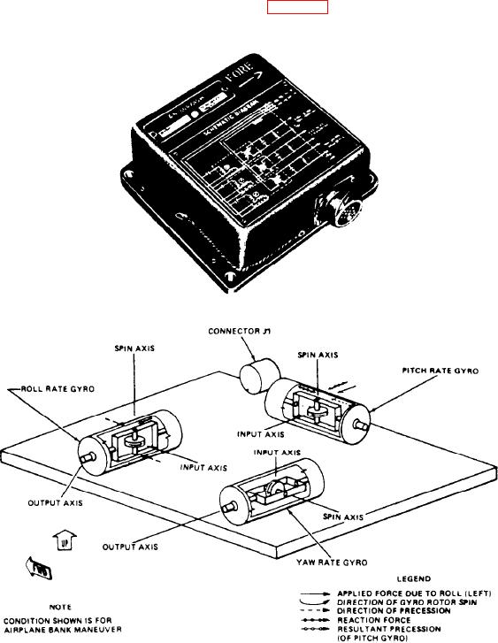
its vertical, lateral, or longitudinal axis. They
bank angle between the aircraft and the surface
provide synchro signal outputs representing yaw
of the earth.
rate, pitch rate, or roll rate to the air navigation
computer. These units are sometimes very similar
When the aircraft yaws, the case, the gimbal,
in appearance to the rate switching gyro, but they
and the gyro stator turn about the rotating gyro
provide entirely different information to the
motor. This has no significant effect upon the
system. Physically, rate gyroscopes are the same.
relative positions between the gyro and the
They differ only in respect to calibration, align-
case. As a result, there are no pitch and bank
ment, range, sensitivity, and natural frequency.
synchro output voltages in response to changes
Each gyro measures angular rate. It uses the
in yaw.
proportional precessional torque generated by the
rate of movement about the gyro-sensitive axis
Three-Axis Rate Gyroscopes. --Rate gyros
(fig. 8-19) to make these measurements.
sense the rate of movement of an aircraft about
Figure 8-19.-Three-axis rate gyro orientation diagram.
8-17