During collective coupler operation with radar
amplifier to the fade-in circuit. The isolation
amplifier output is summed with the vertical
altitude mode engaged, the coupler seeks and
accelerometer signal, and the resultant is com-
retains the altitude selected on the control panel.
bined with the integrator amplifier output.
Any difference between radar altitude and the
When operating in the collective coupler
selected altitude produces an error voltage. This
vertical accelerometer mode, the cable signal is
voltage causes the total lift developed by the rotor
disconnected. In this mode only the vertical
blades to change and seek the selected altitude.
accelerometer and radar altitude signals are
The radar altitude error signal is also fed to the
applied to the output fade-in or fade-out circuit.
integrator amplifier circuit. This circuit provides
During collective coupler operation, accidental
a signal to compensate for a steady-state error
signal input. The compensating signal is added to
momentary disengagement of the altitude control
is prevented by a diode in the ASE control panel.
the other portion of the radar altitude error signal.
This diode makes the momentary BAR REL
The combined signal then couples to an output
button inoperative.
fade-in circuit.
The radar navigation set produces a signal
(vertical velocity) proportional to the rate of
Yaw Channel
change in altitude. This rate signal is lagged
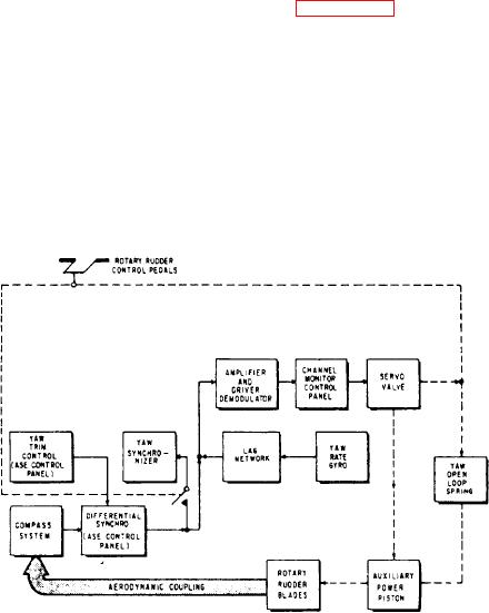
When the ASE is on, the yaw channel
approximately 1 second in the lag amplifier. The
stabilizes the heading of the helicopter. The
rate signal then goes through the ASE control
compass system sends a heading signal to a
panel, and couples to the output fade-in circuit.
The coupler altitude error signal is coupled to the
differential synchro in the ASE control panel.
collective ASE amplifier and processed in a similar
(See figure 8-51.) The physical position of the
manner as the basic ASE altitude error signal.
differential synchro is controlled by the ASE
In the cable attitude mode, the cable altitude
control panel YAW TRIM control. The output
output signal is compared to the radar altitude
of the differential synchro is coupled to the yaw
output signal. Any difference between signals
synchronizer module. Depending on the mode
goes to the follow-up integrator circuit. The
of the yaw channel, the signal becomes a
follow-up output signal is fed back to the cable
synchronizing signal or a heading error signal.
During the synchronizing mode (manual turns
altitude input to correct the cable altitude signal.
The corrected cable altitude input signal is
using cyclic stick and rudder pedals), heading
summed with the ALTITUDE control. The
signals are nulled out and no error signal is
resultant signal is coupled through the isolation
coupled to the yaw ASE amplifier. When the yaw
Figure 8-51.-ASE yaw channel.

