entered the inlet is now expelled at a much higher speed
than when it entered. This causes the engine thrust.
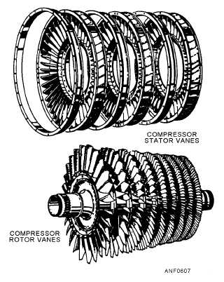
COMPRESSOR.—The axial-flow compressor is
made up of a series of rotating blades and a row of
stationary stator vanes, as shown in figure 6-7. A row of
rotating blades and stator vanes is called a stage. The
entire compressor is made up of a series of alternating
rotor blade and stator vane stages.
You
recall
that
the
compressor
provides
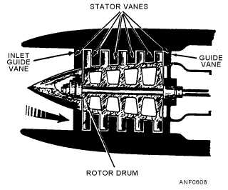
high-pressure air to the combustion chamber (or
chambers). The compressor delivers outside air
(ambient) to the inlet section and passes this air through
the inlet guide vanes. In turn, the inlet guide vanes
deflect the air in the direction of compressor rotation.
The rotating blades arrest the airflow and pass it to a set
of stationary stator vanes. The air is again deflected and
picked up by another set of rotating blades, and so on
through the compressor. The pressure of the air
increases each time it passes through a set of rotors and
stators because the areas of the rotors and stators get
smaller, as shown in figure 6-8.
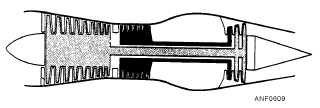
One development in the axial-flow engine is the
split spool compressor. This compressor (fig. 6-9) uses
two rotors of nine and seven stages, respectively. An
assigned wheel drives each rotor of the axial three-stage
turbine assembly. This configuration makes possible
high compressor pressure ratios, which are necessary
for efficient high-altitude operations.
Another development was necessary to eliminate
compressor stall in turbojet engines. The axial
compressor, especially with fixed blading, was subject
to stalling. Compressor stall was normally caused by a
breakdown of the airflow through a few stages of the
compressor. Compressor stall could progress until the
complete unit stalled.
There are two methods to eliminate compressor
stall. The compressor bleed-air system and the variable
vane system. The compressor bleed-air system bleeds
off approximately 10 percent of the front compressor
discharge air. It reduces the amount of air available to
the rear compressor. This provides a surge-free
operation throughout the critical speeds of the engine.
The variable vane system changes the position of the
inlet guide vanes and the stator vanes to avoid
compressor stall. This action maintains the velocity of
the air (and the angle at which it strikes the blades)
within acceptable limits for low airflow conditions. It
also permits high airflow with a minimum of
restriction.
6-5
Figure 6-7.—Stator and rotor components of an axial-flow
compressor.
Figure 6-8.—Five-stage compressor.
Figure 6-9.—Dual rotor turbine for split spool compressor.


