Gases that result from the combustion process have
temperatures of approximately 3,500<F (1,900<C).
Before entering the turbine, these gases must be cooled
to about half this value. The design of the turbine and
the materials used in its makeup determine the
temperature to which the gases must be cooled.
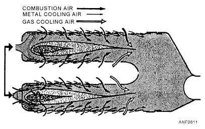
Secondary air, which enters through a set of relatively
large holes located toward the rear of the liner, dilutes
and cools the hot gases. The liner must also be
protected from the high temperatures of combustion.
This is usually done by cool air introduced at several
different places along the liner. The cool air forms an
insulating blanket between the hot gases and the metal
walls, as shown in figure 6-11.
TURBINE.—The turbine assembly drives the
compressor and accessories by extracting some of the
energy and pressure from the combustion gases. In a
typical jet engine, about 75 percent of the power
produced internally is used to drive the compressor.
The remaining 25 percent produces the necessary
thrust.
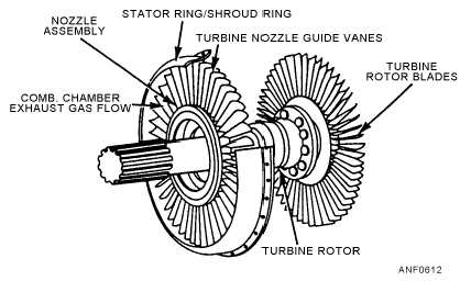
The turbine consists of a nozzle assembly and a
rotating blade assembly. The hot gases from the
combustion chamber flow through the turbine nozzle
assembly and are directed against the rotating turbine
disk blades. The rotating blade assembly (turbine rotor)
is made up of a steel shaft and disk. High-temperature
alloy blades are locked into grooves cut in the periphery
of the disk. The entire turbine rotor is statically and
dynamically balanced. In some units, the turbine
compressor rotors are mounted on the same shaft. In
other units they are mounted on separate shafts that are
connected during assembly.
The nozzle assembly consists of the nozzle guide
vanes and the stator ring/shroud ring, as shown in figure
6-12. The guide vanes are made up of high-temperature
alloy. They are fitted into or welded to the stator
ring/shroud.
6-7
Figure 6-11.—Airflow through a can-annular chamber.
Figure 6-12.—Turbine rotor and nozzle.


