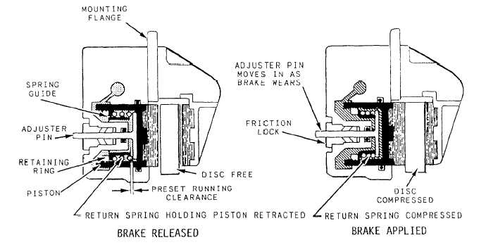
Figure 12–47.—Brake self-adjustment feature—single disc brake.
Proof testing is accomplished by applying 4,500 psi
individualy to each port with the opposing port plugged.
Maintain the pressure for 2 minutes, and there should be
no leakage. Conduct this check a minimum of three
times, and during the last proof test, rotate the swivel
through a complete swiveling circle. Conduct the static
leak test in the same manner as the proof test using 5 to
10 psi. Next, apply 3,000 psi to both the normal and
emergency ports with the opposing ports plugged.
Gradually, apply and check the torque required to rotate
the swivel. Maximum torque required should not exceed
30 inch-pounds.
In the final step of testing, apply low pressure to
each port with the opposing port unplugged, and check
to ensure that fluid flows freely through the swivel. If
the swivel is RFI and is to be returned to supply for stock,
flush it with preservative hydraulic fluid and plug all
ports. If the part fails the testing, tag it to show the part
of the test failed. Flush with preservative hydraulic fluid
and plug the ports. Forward the part to supply to be
forwarded to the next higher level of maintenance.
BRAKE ASSEMBLY MAINTENANCE
Learning Objective: Identify the maintenance
procedures for the single disc, the dual disc,
and the bimetallic disc brake assemblies.
The description and operation of the single disc,
dual disc, multiple disc, and segmented rotor brake
assemblies were covered earlier in this chapter.
Additional maintenance information on the single and
dual disc brake assemblies and a description and
operation of the trimetallic disc brake assemblies are
covered in this section.
SINGLE AND DUAL DISC BRAKES
Automatically adjusted single and dual disc brakes
are designed to provide a satisfactory running clearance
between the brake disc and the brake linings. The
self-adjusting feature of the brake maintains the desired
lining and puck-to-disc clearance, regardless of lining
or puck wear. See figure 12-47. When you apply the
brakes, hydraulic pressure moves each piston and its
pucks or linings against the disc or discs as applicable.
As the linings wear, the piston pushes against the
adjusting pin (through the spring guide) and moves the
pin against the friction of the adjusting pin grip. When
you release the brake pressure, the force of the return
spring moves the piston away from the brake disc, but
it does not move the adjusting pin, which is held by the
friction of the pin grip. The piston moves away from the
disc until it stops against the head of the adjusting pin.
Thus, regardless of the amount of wear, the same travel
of the piston will be required to apply the brake, and the
running clearance will be maintained.
12-53


