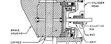
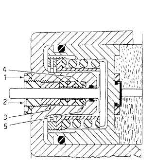
Figure 12–48.—Cross-sectional view of a single disc brake assembly
with captured torquing-type automatic adjuster.
The automatic adjusting feature may be referred to
as a captured torquing type or captured nontorquing
type. Figure 12-48 shows a typical captured
torquing-type automatic adjuster. It is mandatory that
clearance be established between the linings and the
discs before torquing the automatic adjusting nut to the
amount specified for the brake involved. Otherwise, the
brake will drag until an amount equal to the built-in
1. Locknut
4. Grips, split collar
2. Threaded bushing
5. Washer
3. Spacer
Figure 12-49.—Captured nontorquing-type automatic adjuster.
clearance is worn from the face of the linings. With the
adjusting nuts properly torqued, the friction between the
grip and the adjusting pin is great enough to overcome
the compression of the return spring, and the adjusting
pin will be pulled through the grip only to compensate
for lining wear.
After torquing the automatic adjusting nuts to the
specified value, back them off and retorque several
times. This procedure will ensure proper mating of all
parts and the correct torque on the final assembly.
Figure 12-49 shows the captured nontorquing-type
automatic adjuster used on some single and dual disc
brake assemblies.
Brakes that contain nontorquing adjusters can be
identified by the locknut and threaded bushing over each
adjusting pin. The only difference between the torquing-
and nontorquing-type automatic adjustment is the
method used to restrict the movement of the adjusting
pin. The torquing-type adjustment uses a tapered grip,
and the nontorquing uses one or more l/4-inch-wide
grips composed of brass liners.
12-54