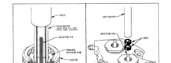
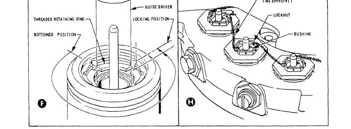
Figure 12-52.—Seal replacement and piston return adjustment—Continued.
remove the locknuts, bushings, spacers, and grips from
adjusting pins, as shown in view E. Hold the guides in
the housing. Remove the spring retaining ring from
the bottomed position and turn the threaded retaining
within the piston, as shown in view D.
rings clockwise until the rings are snug against the
With the linings still attached to the pistons, support
bottom guides. Back off the threaded retaining rings 3/4
the pistons in a press. Use a 3-inch length of 7/8-inch
of a turn counterclockwise from the bottomed positions
steel tubing to force the guides to the bottom on the
and, if necessary, continue turning counterclockwise to
12-59


