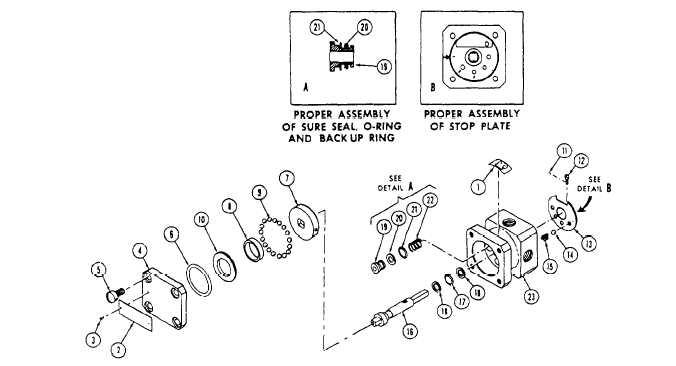
1. Decal
6.
2. Nameplate
7.
3. Drive screw
8.
4. Retainer plate
9.
5. Machine screw 10.
O-ring
11. Thread lock
16. Actuating shaft
21. Backup ring
Shear plate assembly 12. Lock screw
17. O-ring
22. Seal spring
Ball retainer
13. Stop plate
18. Backup ring
23. Body assembly
Balls
14. Ball
19. Sure seal
Bearing plate
15. Detent spring
20. O-ring
Figure 12–45.—Brake selector valve—exploded view.
This procedure completes the thermal crack test. In
preparation for the shuttle valve opening operation test
that follows, block residual pressure in the BRAKE port
using a pressure gauge as the plug.
With the RET port open and BRAKE port capped,
apply hand-pumped hydraulic pressure gradually to the
PMV port. There should be a simultaneous increase of
BRAKE port pressure with PMV port pressure. At a
pressure of 60 to 80 psi in the PMV port, pressure in the
PMV port and BRAKE port should become equal. A
gradual increase in PMV port pressure to 1,500 psi should
result in a proportionate increase in the BRAKE port
pressure. Any displacement at the RET port should not
be considered leakage during this phase of the bench test.
The shuttle valve closing operation test begins with
1,500 psi from the previous phase still applied to the
PMV port. Reduce the pressure at the PMV port to 150
psi, and then rapidly to 0 psi. The closing operation is
evidenced by the venting of hydraulic fluid from the
RET port as PMV pressure decreases from 20 psi to 0 psi.
The final phase of the bench test is the test for
leakage. This phase is started with 27-psi hydraulic
pressure trapped in the BRAKE port. There should be
no evidence of pressure decrease when it is measured
over a period of 3 minutes. Continue the test with the
BRAKE port capped and the RET port of the valve in
an upright position. Fill the RET port cavity and a
leakage measuring device with hydraulic fluid. Apply
hand-pumped hydraulic pressure of 30 to 37 psi to the
PMV port. Leakage at the RET port must not exceed 0.5
cubic centimeter per minute. Immediately after
application of pressure, measure the leakage for a
3-minute period. Disregard volume displacement
because of shuttle valve transition if leakage is not in
excess of 0.5 cubic centimeter per minute. Increase the
pressure to 125 psi and maintain for a 3-minute period.
There should be no evidence of leakage. Further
increase the pressure to 1,500 psi and maintain for
another 3-minute period. There should be no leakage.
BRAKE SELECTOR VALVE
Repair of the brake selector valve at the
intermediate level of maintenance is limited to the
replacement of cure-date items and parts listed under
Spares and Replacement Parts Data in the "Intermediate
Maintenance” section of the MIM.
Figure 12-45 shows an exploded
selector valve. Observe the arrangement
view of the
in which the
12-51