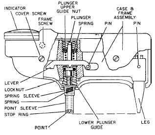
Figure 1-30.—Cutaway of Barcol tester.
Figure 1-30 is a cutaway drawing of the tester,
showing the internal parts and their general arrangement
within the case.
The lower plunger guide and point are accurately
ground so that attention need be given only to the proper
position of the lower plunger guide within the frame to
obtain accurate operation when a point is replaced.
The frame, into which the lower plunger guide and
spring-tensioned plunger are screwed, holds the point in
the proper position. Adjustment of the plunger upper
guide nut, which regulates the spring tension, is made
when the instrument is calibrated at the factory.
CAUTION
The position of this nut should not be
changed. Any adjustment made to the
plunger upper guide nut will void the
calibrated settings made at the factory.
The leg is set for testing surfaces that permit the
lower plunger guide and the leg plate to be on the same
plane. For testing rivets or other raised objects, a block
may be placed under the leg plate to raise it to the same
plane. For permanent testing of this type, the leg maybe
removed and washers inserted, as shown in the drawing.
The point should always be perpendicular to the surface
being tested.
The design of the Barcol tester is such that operating
experience is not necessary. It is only necessary to exert
a light pressure against the instrument to drive the
spring-loaded indenter into the material to be tested. The
Table 1-5.—Typical Barcol Readings for Aluminum Alloys
Alloy and temper
Barcol number
1100-0
35
3003-0
42
3003 -1/2H
56
2024-0
60
5052-0
62
5052-1/2H
75
6061-T
78
2024-T
85
hardness reading is instantly indicated on the dial.
Several typical reading for aluminum alloys are listed in
table 1-5. The harder the material, the higher the Barcol
number.
To prevent damage to the point, avoid sliding or
scraping when it is in contact with the material being
tested. If the point should become damaged, it must be
replaced with a new one. No attempt should be made to
grind the point.
Each tester is supplied with a test disc for checking
the condition of the point. To check the condition of the
point, press the instrument down on the test disc. When
the downward pressure brings the end of the lower
plunger guide against the surface of the disc, the
indicator reading should be within the range shown on
the test disc.
To replace the point, remove the two screws that
hold the halves of the case together. Lift out the frame,
remove the spring sleeve, loosen the locknut, and
unscrew the lower plunger guide, holding the point
upward so that the spring and plunger will not fall out
of place. Insert the new point and replace the lower
plunger guide, screwing it back into the frame, Adjust
the lower plunger guide with the wrench that is
furnished until the indicator reading and the test disc
average number are identical. After the lower plunger
guide is properly set, tighten the locknut to keep the
lower plunger guide in place, This adjustment should be
made only after installing anew point; any readjustment
on a worn or damaged point give erroneous readings.
1-40