Automatic Check Valves
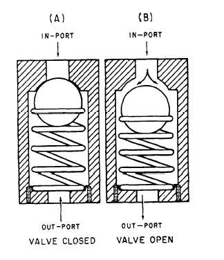
Automatic check valves contain a seat on which a
movable body (ball, cone, or poppet) seats by means
of spring tension. See figure 8-12. The valve opens
when pressure in the direction of flow (indicated by
an arrow on the body of the valve) is strong enough to
unseat the movable body. Flow in the reverse
direction, along with spring tension, tends to seal the
movable body against the valve seat.
When the pressure on the downstream side of the
valve exceeds that on the upstream side, the resultant
unbalanced force seals the valve closed, as shown in
view A of figure 8-12. When the pressure is reversed,
the valve is forced open against the tension of the
spring, and the fluid flows freely through the valve, as
shown in view B of figure 8-12. The tension of the
spring is relatively weak, and is intended to be barely
sufficient to support the ball in its proper position.
Bypass Check Valves
Bypass check valves serve the same purpose as
automatic check valves, but are so constructed that
they may be opened manually to allow the flow of
fluid in both directions. An example of the possible
use of a bypass check valve is in the line between the
hand pump and the accumulator. Installation of a
Figure 8-12.—Typical check valve.
bypass check valve in this line would allow hand
pump pressure to be directed to either the accumulator
or the selector valve.
Maintenance of Check Valves
Check valves require little attention over long
periods of time.
Leakage may be caused by the
presence of a tiny particle of foreign matter between
the checking device (ball, cone, or poppet) and its
seat. To remove the foreign matter, it is necessary to
remove the valve from the aircraft and completely
disassemble the valve. If no scratches are found on
the valve seat or the checking device, wash all parts in
clean hydraulic fluid of the same type as that used in
the system.
While the valve is disassembled, inspect the
housing and the checking device for evidence of
corrosion. Replace the valve if there is corrosion or
excessive roughness. A slightly rough surface can be
smoothed by buffing. A cone-type check valve may
have a tendency to lean to one side, in which case the
movable part may dig into the soft aluminum body of
the housing and stick there.
When installing a check valve, remember that the
arrow marked on the housing must point in the
direction of the flow of the fluid through the valve.
Before removing a check valve from a line, it is good
practice to mark the adjacent structure, indicating the
direction in which the arrow points. Also, observe the
following precaution during installation of check
valves: Grip the wrench flats of the check valve at the
end to which the connecting tubing is being installed.
Do not grip the opposite end. This will prevent the
possibility of distorting the valve body, causing the
valve to leak.
SEQUENCE VALVES
Sequence valves are used to control a sequence of
operations; they ensure that actuating units operate at
the proper time and in the proper sequence. Sequence
valves may be mechanically operated or
pressure-operated valves. An example of the use of a
sequence valve is in a landing gear actuating system.
In a landing gear actuating system, the landing
gear doors must open before the landing gear starts to
extend. Conversely, the landing gear must be
retracted before the doors close. A sequence valve
installed in each landing gear actuating line performs
this function.
8-16


