One-Way Restrictor
One-way restrictors provide reduced hydraulic
flow in one direction only, to limit actuating speed of
hydraulic cylinders for the purpose of proper timing
or sequence of operation. Also, they provide free
flow of fluid in the opposite direction to permit the
actuating cylinder to actuate at a faster rate of speed
during the reverse action of the cylinder.
One-way restrictors are used in some landing gear
systems to regulate the speed and sequence of landing
gear retraction or extension. If sequenced action (that
is, one cylinder to be actuated before other cylinders
on the same line) is desired, one-way restrictors are
placed in the line upstream of all cylinders except one.
Figure 8-16 shows both the one-way and two-way
restrictors. The main parts of a one- way restrictor are
the cylindrical body and cap, which contain a
spring-loaded poppet, a cage, and a stainless steel
filter element.
The one-way restrictor allows free flow in one
direction and restricted flow in the opposite direction.
Both directions of flow are indicated by arrows found
on the body of the valve.
In a restricted direction, pressurized fluid entering
port R (fig. 8-16) flows through the filter assembly
and enters the cage through drilled passages. Fluid
from the interior of the cage is forced through the
poppet’s orifice, thus causing the required metering
action.
In the free flow direction, pressurized fluid
entering port F overcomes poppet spring tension and
allows fluid to flow past the poppet’s seat, through
drilled passages within the larger flange of the cage,
and out through port R.
Two-Way Restrictor
Two-way restrictors are used to limit the flow of
hydraulic fluid where it is desirable to retard the
action of a hydraulic cylinder in both directions.
Figure 8-16 shows two types of two-way restrictors,
one of which has a machined orifice with two integral
stainless steel filters. The other type shown contains
an orifice plate between two stainless steel filters.
The filters contained within the restrictors are
identical in construction and provide protection in
both directions of flow. The filter size specification
for the two-way restrictor is identical to those found
within one-way restrictors.
Two-way restrictors, regardless of whether they
are of the machined orifice type or of the plate orifice
type, operate identically. Fluid entering either port is
filtered prior to flowing through the orifice, thus
protecting the orifice from possible stoppage. As the
fluid is metered through the orifice, the prescribed
rate flow is directed out the opposite port of the
restrictor and to the actuating unit.
Maintenance of Restrictors
Maintenance of restrictors is usually limited to
checking for external leakage and the required fluid
flow. The specific MIM lists the required fluid flow
in gallons per minute (gpm) for each size of orifice
being checked. It also specifies the correct pressures
to use as well as the required procedures during each
check.
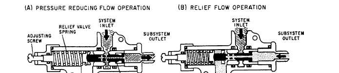
PRESSURE-REDUCING VALVES
Pressure-reducing valves are used in hydraulic
systems where it is necessary to lower the normal
system operating pressure a specified amount.
Figure 8-17 shows the operation of a
pressure-reducing valve. View A of figure 8-17
shows system pressure being ported to a subsystem
Figure 8-17.—Pressure-reducing valve operational schematic.
8-21