(or power control cylinder) built into the control
linkage.
PRIMARY FLIGHT CONTROL
SYSTEMS
Learning Objective: Recognize the functions
of the three primary flight control systems
(longitudinal, lateral, and directional) and
the maintenance associated with each
system.
Different aircraft manufacturers call units of the
primary flight control system by a variety of names.
The types and complexity of control mechanisms
used depend on the size, speed, and mission of the
aircraft.
A small or low-speed aircraft may have
cockpit controls connected directly to the control
surface by cables or pushrods. Some aircraft have
both cable and a pushrod system. See figure 9-1. The
force exerted by the pilot is transferred through them
to the control surfaces. On large or high-performance
aircraft, the control surfaces have high pressure
exerted on them by the airflow. It is difficult for the
pilot to move the controls manually. As a result,
hydraulic actuators are used within the linkage to aid
the pilot in moving the control surface. Figure 9-2
shows a mechanically controlled, hydraulically
assisted system. Because these systems reduce pilot
fatigue and improve system performance, they are
now commonly used.
Such systems include
automatic pilot, automatic landing systems, and
stability augmentation systems.
Navy specifications require two separate
hydraulic systems for operating the primary flight
control surfaces. Current specifications call for an
independent hydraulic power source for emergency
operation of the primary flight control surfaces.
Some manufacturers provide an emergency system
powered by a motor-driven hydraulic pump. Others
use a ram-air-driven turbine
emergency system pump.
LONGITUDINAL CONTROL
for operating the
SYSTEMS
Longitudinal control systems control pitch about
the lateral axis of the aircraft. Many aircraft use a
conventional elevator system for this purpose.
Aircraft that operate in the higher speed ranges
usually have a movable horizontal stabilizer.
Elevator Control System
The elevator control system, shown in figure 9-2,
is typical of many conventional elevator systems. It
operates by the control stick in the cockpit and is
hydraulically powered.
The operation of the elevator control system
starts when the control stick is moved fore or aft.
The movement of the stick transfers through the
control cables to move the elevator control bell
crank. The bell crank transmits the movement to
the hydraulic actuating cylinder through the control
linkage. The hydraulic actuating cylinder operates
a push-pull tube, which deflects the elevators up or
down.
The elevator system uses forward and aft
bobweights. The bobweights induce a load on the
control stick during pitching and vertical acceleration
and prevent pilot-induced oscillations through the
elevator controls. If the gravity force is increased on
the bobweights, the induced load tends to return the
control stick to the neutral position. Viscous dampers
on the bobweight assemblies retard control stick
movement to prevent overcontrol. Overcontrol could
cause airframe overstress.
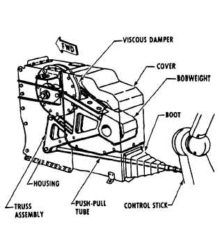
The elevator forward bobweight serves to help
recenter the control stick when a heavy gravity load
pulls against the airframe. The forward bobweight
and damper assembly is in a housing forward of the
control stick in the cockpit. See figure 9-3. The
Figure 9-3.—Elevator forward bobweight and damper
assembly.
9-3