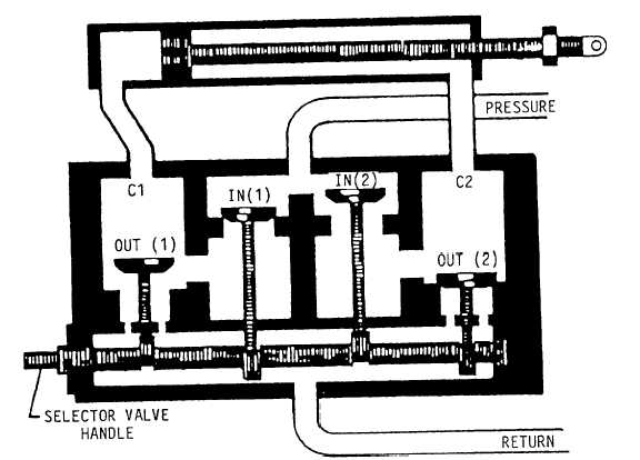
You can rotate the camshaft by moving the
control handle in either direction from neutral. This
action rotates the lobes, which unseat one pressure
poppet and one return poppet. See figure 8-9. The
valve is now in a working position. Pressure fluid,
entering the pressure port, travels through the vertical
fluid passages in both pressure poppet seats. Since
only one pressure poppet is unseated by the cam lobe,
the pressure fluid flows past this open poppet to the
inside of the poppet seat. From there it flows out the
diagonal fluid passages, and then out one cylinder
port and to the actuator.
Return fluid coming from the actuator is coming
in the other cylinder port, through the diagonal fluid
passages, past the unseated return poppet, through the
vertical fluid passages, and out the return port to the
system reservoir. By rotating the camshaft in the
opposite direction until the stop pin hits, the opposite
pressure and return poppets are unseated, and the
fluid flow is reversed. This causes the actuator to
move in the opposite direction.
Selector valves should be checked periodically
for leakage and security of mounting. The operating
linkage should be inspected for ease of operation.
Malfunctioning selector valves are usually the
result of foreign particles or damaged parts. A
malfunctioning valve should be removed and checked
for free movement of the camshaft. The valve maybe
disassembled and all parts cleaned with clean
hydraulic fluid. O-rings should be replaced while the
valve is disassembled.
Both external and internal leakage may be caused
by damaged or worn O-rings. External leakage could
be caused by a damaged gasket under the sealing plug
or the end packing on the camshaft. Internal leakage
could be caused by a damaged center packing on the
camshaft, a damaged bottom gasket on the poppet
seat, or a damaged O-ring packing on the poppet.
NOTE: All selector valves that require repair
or adjustment must be done in accordance
with the applicable MIM or 03 manual. After
repair or adjustment, all valves must be tested
for proper operation and leakage.
Figure 8-9.—Working view of a poppet-type selector valve.
8-11