MULTIPLE/TRIMETALLIC DISC BRAKES
Multiple disc brakes are heavy-duty brakes
designed for use with power brake control valves or
power boost master cylinders. The brake assembly
consists of a bearing carrier bearings and retaining nut;
the annular actuating piston; and the heat stack, which
is composed of a pressure plate, rotating discs (rotors),
stationary discs (stators) and backup plate, an automatic
adjuster, retracting springs, and various other
components.
Regulated hydraulic pressure is applied through the
automatic adjuster to a chamber in the bearing carrier.
The bearing carrier is bolted to the shock strut axle
flange and serves as a housing for the annular actuating
piston. Hydraulic pressure forces the annular piston to
move outward, compressing the rotating discs, which
are keyed to the landing wheel, and the stationary discs,
which are keyed to the bearing carrier. The resulting
friction causes a braking action on the wheel and tire
assembly.
When the hydraulic pressure is relieved, the
retracting springs force the actuating piston to retract
into the housing chamber in the bearing carrier. The
hydraulic fluid in the chamber is forced out by the return
of the annular actuating piston, and is bled through the
automatic adjuster to the return line. The automatic
adjuster traps a predetermined amount of fluid in the
brake–an amount just sufficient to give correct
clearances between the rotating discs and stationary
discs. See figure 12-33.
The trimetallic disc type brakes are used on most
naval aircraft. They operate on the same basic principle
as the multiple disc brakes and will be discussed in detail
later in this chapter.
SEGMENTED ROTOR BRAKES
Segmented rotor brakes are heavy-duty brakes,
especially adapted for use with high-pressure hydraulic
systems. These brakes may be used with either power
brake control valves or power boost master cylinders.
Braking is accomplished by means of several sets of
stationary, high-friction type of brake linings making
contact with rotating (rotor) segments. A cutaway view
of the brake is shown in figure 12-34. As you can see,
the segmented rotor brake is very similar to the multiple
disc type, described in the previous section.
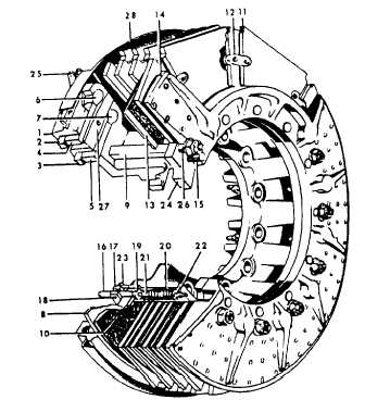
The brake assembly consists of a carrier, two
pistons and piston cup seals, a pressure plate, an
auxiliary stator plate, rotor segments, stator plates, a
1.
2.
3.
4.
5.
6.
7.
8.
9.
10.
11.
12.
13.
14.
Carrier assembly
Piston cup (outer)
Piston cup (inner)
Piston (outer)
Piston (inner)
Piston end (outer)
Piston end (inner)
Pressure plate
Stator drive sleeve
Auxiliary stator and
lining assembly
Rotor segment
Rotor link
Stator plate
Backing plate
15.
16.
17.
18.
19.
20.
21.
22.
23.
24.
25.
26.
27.
28.
Torque pin
Adjuster pin
Adjuster clamp
Adjuster screw
Adjuster washer
Adjuster return spring
Adjuster sleeve
Adjuster nut
Clamp holddown
assembly
Shim
Bleeder screw
Drive sleeve bolt
Dust cover (inner)
Dust cover (outer)
Figure 12-34.-Segmented rotor brake–cutaway view.
compensating shim, automatic adjusters, and a backing
plate.
BRAKE SYSTEM MAINTENANCE
Learning Objective: Identify the two primary
brake systems and the checks required to make
sure these systems operate properly.
Brake systems are designed to retard or to stop
aircraft motion on the ground. They also aid in
controlling the direction of the aircraft while it is taxiing.
Provisions exist for applying either one or both brakes
12-39