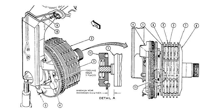
1. Primary disc assembly
5.
2. Rotors
6.
3. Stators
7.
4. Power plate assembly
8.
Bleed valve
Primary disc lining face
Secondary disc insulation
Secondary disc assembly
Figure 12–36.-Wheel brake.
The next steps of the fictional checkout require
that the wheel and tire assemblies be removed and
hydraulic power reapplied. Depress the brake pedals for
approximately 1 minute, and check each power plate for
hydraulic leakage.
Check lining wear by depressing the brake pedals.
Measure the gap between the face of the primary disc
assembly (1) and the screw thread insert (11). See figure
12-36. Lining wear should not exceed 0.816 inch. Check
running clearance by first applying the brake pedals
until 1,200 psi is indicated on the gauges installed in the
brake bleed ports. Measure the distance between the
primary disc and the face of the screw thread insert.
Release the brakes and measure the distance again.
Subtract this dimension from that obtained with the
brakes applied to obtain the running clearance.
Clearance should be 0.070 to 0.119 inch.
Brake Wear Check
Lining wear may be checked by two methods.
Before checking the brakes on any aircraft, always refer
to the applicable MIM and use the method
recommended by the aircraft manufacturer.
9. Pneumatic pressure line
10. Hydraulic pressure line
11. Screw thread insert (5 each)
WEAR CHECK METHOD (NO. 1).—Have a
person in the cockpit apply the brake, and with the brake
applied, measure the distance between the face of the
brake disc and the brake housing, as shown in figure
12-37. If this distance has progressed to the maximum
specified measurement given in the MIM, the brake
should be removed and disassembled, and the lining
pucks inspected for wear.
NOTE: Linings can be measured only by
removing and disassembling the brake. If any
puck has worn to a thickness of less than
one-sixteenth inch, the entire set must be
replaced. NEVER MIX NEW AND USED
LININGS.
WEAR CHECK METHOD (NO. 2).—In using this
method, have a person in the cockpit apply the brake.
With the brake applied, check the position of the
automatic adjusting pins (fig. 12-38). If any adjusting
pin recedes inside the adjusting pin nut (one-sixteenth
to three-eighth inch, the exact amount depending on the
brake model), the brake must be removed and
disassembled, and the lining thickness checked. If any
12-42


