prevents loss of hydraulic fluid in the event of utility
or normal system rupture.
As a minimum requirement, filters are provided in
each system pressure line, return line, and pump bypass or
case drain line. Where hydraulic sequencing is critical,
each sequence valve is protected from contamination in
each direction of flow by a screen-type filter. The filter is
usually included as a part of the sequence valve. The
pressure line falters clean all fluids before they enter any
major equipment. If there are only two hydraulic systems,
the primary system is known as the No. 1 power control
system (PC-1). The system supplying the other half of the
flight control tandem actuating mechanisms and the utility
hydraulic system is known as PC-2. The PC-2 system is
also known as the combined hydraulic system. If there are
three hydraulic power systems, they are generally identified
as PC-1, PC-2, and utility system. Some manufacturers
label the utility system PC-3. Each system has its own
reservoir, hydraulic pump(s), and plumbing.
Military specifications, MIL-H-5440 (series),
provide complete design, installation, and data
requirements for aircraft hydraulic systems. These
specifications provide reference to all other specifications
concerning aircraft hydraulic systems. Items such as hose
assemblies, hose support requirements, minimum bend
radii, types of pumps, and types and classes of systems are
found in the specifications.
Many maintenance instruction manuals (MIMs)
refer to aircraft hydraulic systems as being open
center or closed center systems. The following
paragraphs provide a discussion of these systems.
Open Center
An open center system is one having fluid flow, but
no pressure in the system when the actuating mechanisms
are idle. The pump circulates the fluid from the reservoir,
through the selector valves, and back to the reservoir.
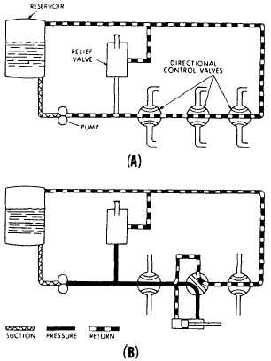
Figure 7-1 shows a basic open center system. The open
center system may employ any number of subsystems,
with a selector valve for each subsystem. Unlike the
closed center system, the selector valves of the open
center system are always connected in series with each
other. In this arrangement, the system pressure line goes
through each selector valve, Fluid is always allowed free
passage through each selector valve and back to the
reservoir until one of the selector valves is positioned to
operate a mechanism.
When one of the selector valves is positioned to
operate an actuating device, fluid is directed from the
pump through one of the working lines to the actuator.
See view B of figure 7-1. With the selector valve in
this position, the flow of fluid through the valve to the
reservoir is blocked. The pressure builds up in the
system to overcome the resistance and moves the
piston of the actuating cylinder, The fluid from the
opposite end of the actuator returns to the selector
valve and flows back to the reservoir. Operation of
the system following actuation of the component
depends on the type of selector valve being used.
Several types of selector valves are used in conjunction
with the open center system. One type is both manually
engaged and manually disengaged. First the valve is
manually moved to an operating position. Then, the
actuating mechanism reaches the end of its operating cycle,
and the pump output continues until the system relief valve
relieves the pressure. The relief valve unseats and allows
the fluid to flow back to the reservoir. The system pressure
remains at the relief valve set pressure until the selector
valve is manually returned to the neutral position. This
action reopens the open center flow and allows the system
pressure to drop to line resistance pressure.
The manually engaged and pressure disengaged
type of selector valve is similar to the valve pre-
viously discussed.
When the actuating mechanism
reaches the end of its cycle, the pressure continues to
rise to a predetermined pressure. The valve auto-
matically returns to the neutral position and to open
center flow.
Closed Center
In the closed center system, the fluid is under
pressure whenever the power pump is operating.
Figure 7-2 shows a complex closed center system.
Figure 7-1.—Basic open center hydraulic system.
7-2