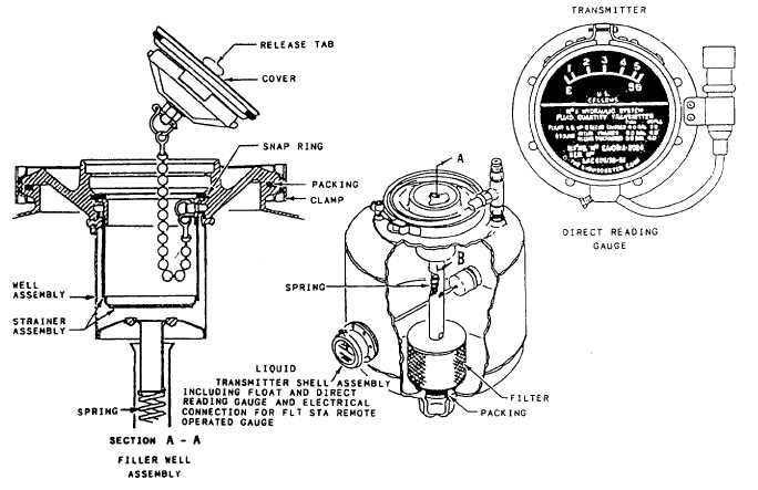
A typical nonpressurized reservoir is shown in
figure 7-4, This reservoir consists of a welded body
and cover assembly clamped together. Gaskets are
incorporated to seal against leakage between
assemblies.
QUANTITY INDICATING GAUGE.—The
reservoir fluid quantity is indicated through a
mechanically operated float and arm (liquidometer)
type of unit. The quantity gauge is mounted directly
on the side of the reservoir. As shown in figure 7-4,
the float and arm unit extends into the reservoir. The
shell of the liquidometer provides a glass window
over a pointer and dial, with the pointer mechanically
linked to the float arm. As the float arm moves to
correspond to the fluid level, the pointer, through
mechanical linkage, moves to indicate the quantity
available. This provides a direct reading sight gauge
at the reservoir.
This same float movement actuates the
potentiometer wiper arm of an integral transmitter
potentiometer. The remote indicating circuit is
energized, and a duplicate indication of the reservoir
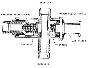
Figure 7-5.—Pressure and vacuum relief valve.
fluid quantity may be seen in the cockpit on a remote
gauge.
RESERVOIR PRESSURE AND VACUUM
RELIEF VALVE.—Although the reservoir shown in
figure 7-4 is classified as a nonpressurized type, it has
a sufficient amount of pressurization to ensure a
7-8
Figure 7-4.—Nonpressurized reservoir.


