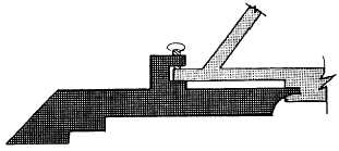
Figure 13-26.—Finger secured in box and pan brake.
Forming Machines
A sheet metal object made on a brake will have
corners (bends) and sides (flanges). On a forming
machine, it is possible to make an object without
sides. For example, you can make a circular object
such as a funnel. The forming machines used in the
Navy are usually located at aircraft intermediate
maintenance departments (AIMDs). The two most
common machines are the slip roll and the rotary.
SLIP-ROLL FORMING MACHINE.—Sheet
metal can be formed into curved shapes over a pipe or
a mandrel, but the slip-roll forming machine is easier
to use and produces more accurate bends. Rolling
machines are available in various sizes and capacities.
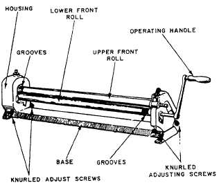
Some are hand operated, like the one shown in
figure 13-27, and others are power operated.
The machine shown in the illustration has two
rolls in the front and one roll at the rear. You can
adjust screws on each end of the machine to control
Figure 13-27.—Slip-roll forming machine.
the distance between the front rolls. By varying the
adjustments, the machine can be used to form
cylinders, cones, and other curved shapes. The front
rolls grip the metal and pull it into the machine;
therefore, the adjustment of distance between the two
front rolls is made on the basis of the thickness of the
sheet being worked.
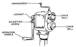
ROTARY MACHINE.—The rotary machine,
shown in figure 13-28, is used on cylindrical and flat
sheet metal to shape the edge or to form a bead along
the edge. Various shaped rolls can be installed on the
rotary machine to perform these operations, which are
described later in the text.
SHEET METAL FABRICATION
Learning Objective: Recognize the terms and
procedures for the fabrication of sheet metal
parts.
To effectively construct and repair parts of an
airframe, you must be able to lay out, cut, and form
metal. The layout of bend lines must include the
allowance for the amount of material used to make the
bend in the proper location. The proper fit of the
finished part can be ensured if the layout, cuts, and
bends are carefully considered before the actual
fabrication is started. The procedures and equipment
discussed in this chapter are designed to provide
accurate and dependable results.
The development of a layout on sheet metal is
basically the same as the development of blueprints
and drawings. For a better understanding of these
procedures, you should refer to Blueprint Reading
and Sketching, NAVEDTRA 1OO77-F1.
Figure 13-28.—Rotary machine.
13-17


