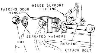
Figure 12-7.–Adjustable door hinge installation.
Landing gear doors have specific allowable
clearances that must be maintained between doors and
the aircraft structure or other landing gear doors. These
required clearances can be maintained by adjusting the
door hinges and connecting links and trimming excess
material from the door if necessary.
On some installations, door hinges are adjusted by
placing the serrated hinge and serrated washers in the
proper position and torquing the mounting bolts, which
allows linear adjustments. Figure 12-7 shows this type
of mounting. The amount of linear adjustment is
controlled by the length of the elongated bolt hole in the
door hinge.
SHOCK STRUTS
Shock struts are self-contained hydraulic units.
They carry the burden of supporting the aircraft on the
ground and protecting the aircraft structure by absorbing
and dissipating the tremendous shock of landing. Shock
struts must be inspected and serviced regularly for them
to function efficiently. This is one of your important
responsibilities.
Each landing gear is equipped with a shock strut. In
addition to the landing gear shock struts, carrier aircraft
are equipped with a shock strut on the arresting gear.
The shock strut’s primary purpose is to reduce arresting
hook bounce during carrier landings.
Because of the many different designs of shock
struts, only information of a general nature will be
included in this chapter. For specific information on a
particular installation, you should refer to the applicable
aircraft MIM or accessories manual.
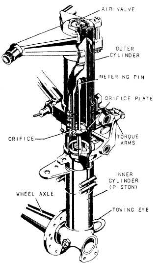
A typical pneumatic/hydraulic shock strut
(metering pin type) is shown in figure 12-8. It uses
compressed air or nitrogen combined with hydraulic
fluid to absorb and dissipate shock, and it is often
Figure 12-8.–Landing gear shock strut (metering pin type).
referred to as the “air-oil” type strut. This particular strut
is designed for use on the main landing gear.
As shown in the illustration, the shock strut is
essentially two telescoping cylinders or tubes, with
externally closed ends. When assembled, the two
cylinders, known as cylinder and piston, form an upper
and lower chamber for movement of the fluid. The lower
chamber is always filled with fluid, while the upper
chamber contains compressed air or nitrogen. An orifice
(small opening) is placed between the two chambers.
The fluid passes through this orifice into the upper
chamber during compression, and returns during
extension of the strut.
Most shock struts employ a metering pin similar to
that shown in figure 12-8 to control the rate of fluid flow
from the lower chamber into the upper chamber. During
the compression stroke, the rate of fluid flow is not
constant, but is controlled automatically by the variable
shape of the metering pin as it passes through the orifice.
12-8