instructions provided in the applicable aircraft
MIM.
NOTE: While performing maintenance on any
system, ensure that the step-by-step procedures
outlined in the MIM including CAUTIONS,
WARNINGS, and SAFETY notes concerning the
specific procedures are strictly complied with.
7. Conduct a final operational check. The
affected component or system must be given an
operational check following installation or repair
to verify proper system or component operation.
The MIM will provide the procedures for
conducting the operational check. It will usually
require operation of the system in various modes
(manual and automatic for air-conditioning and
pressurization systems) or through several cycles,
as applicable. Specified steps throughout the
repair procedure and operational check must be
observed and certified by a quality assurance
representative or a collateral duty quality
assurance representative from the work center
performing the work. These steps are usually
identified in the MIM by underlining, italics, or
some other obvious method.
MULTIMETER TROUBLESHOOTING
SKILLS
As previously mentioned, much of the AME’s
time is spent troubleshooting equipment in the
squadron’s aircraft. Troubleshooting on the S-3
aircraft environmental control system involves the
use of the multimeter to check the resistance of
the temperature sensor and to check the voltage
to electrical connectors. The material presented
in the following paragraphs will increase your
knowledge of the multimeter and increase your
proficiency as a troubleshooter. If you are not sure
of the proper and safe methods for using this
equipment, you should request the assistance of
an AE.
Multimeter
A multimeter is the most common electrical
measuring device used in the Navy. The name
multimeter comes from the words MULTIple
METER. The multimeter is a direct current (de)
ammeter, an alternating current (at) ammeter, a
dc voltmeter, an ac voltmeter, and an ohmmeter
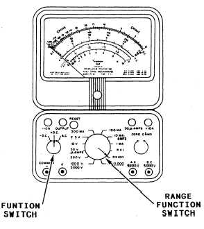
all in one package. Figure 3-23 is a sketch of a
typical multimeter. While it may look
complicated, it is very easy to use.
Figure 3-23.—A typical multimeter.
JACKS.— The lower portion of the meter
contains the function switches and jacks for the
meter leads. The COMMON or ( – ) jack is used
in most functions of the meter. One meter lead
is plugged into the common jack. The ( + ) jack
is used for the second meter lead for any of the
functions printed beside the range function switch
(the large switch in the center). The other jacks
have specific functions printed above or below
them and are self-explanatory. The output jack
is used with the dB scale and will not be explained.
To use one of the special function jacks, except
the + 10 amps, one lead is plugged into the
common jack, and the range function switch is
positioned to point to the special function desired.
For example, to measure a very small current
(20 microampere), one meter lead is plugged
into the common jack, the other meter lead is
plugged into the 50 amps jack, and the function
switch is placed in the 50V/u amps position. To
measure currents above 500 milliamperes, the
+ 10A and – 10A jacks are used for the meter
leads, and the function switch is placed in the
10MA/AMPS position.
FUNCTION SWITCHES.— The function
switch is used to select the function desired. The
– dc, + dc, ac switch selects director alternating
current and changes the polarity of the direct
current functions. To measure resistance, this
switch should be in the + dc position.
3-37