A yellow-colored sealing ring is pressed on each end
of the munition as a seal between the munition and the
tube body. This prevents gas pressure from escaping
during ejection. A green-colored arming cap is installed
on the timer end of a flare or on the rotochute end of a
sonobuoy. The green arming cap lanyard is connected
to the timer knob of the flare, and then pressed on over
the flange of the sealing ring. When you install an
arming cap on the sonobuoy, the lanyard is not used.
Mount a white cross-shaped plastic spacer on the aft
sealing ring of the forward munition. This provides
enough space between the forward and aft munition to
provide an expansion chamber for ejecting the aft
munition.
After you have installed the adapter, install the
munitions in the dispenser tube.
When a SUU-25F/A dispenser is fully loaded and
uploaded on the aircraft, the pilot may eject flares. The
pilot must first select the weapons control system, and
then trigger the dispensing switch. A 28-volt dc
electrical signal passes through an electrical cable from
the aircraft to either receptacle J1 or J2 of the dispenser.
The signal is routed from the dispenser receptacle to the
stepper switch, causing the stepper switch to step from
the preset ARM position to the No. 1 position. This fires
the No. 1 impulse cartridge. The gas pressure, generated
by the fired cartridge, is ported through a gas tube,
internally along the side of the dispenser, into the aft
expansion chamber ahead of the aft flare.
As the gas pressure increases, the aft retaining lock
shear pin is cut, allowing the aft flare to eject. As the
timer end of the flare approaches the rear of the tube,
the arming finger of the arming mechanism engages the
yellow sealing ring. The sealing ring cams the arming
finger down, which, in turn, cams the arming hook up
to engage the green arming cap. This action allows the
flare to extend the lanyard. The lanyard extracts the
timer knob and arms or starts the flare functioning
sequence.
When the pilot triggers the system again, the stepper
switch steps to the No. 2 position and fires the cartridge.
This meters the gas pressure directly into the forward
expansion chamber. As the gas pressure increases, the
forward retaining lock shear pin is cut. This allows the
forward flare to be dispensed in the same manner as the
aft flare. If the aft flare failed to eject, the gas pressure
generated for ejecting the forward flare produces
sufficient gas pressure to purge both flares out of the
tube.
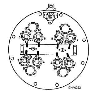
The procedure for the remaining three tubes is the
same. The firing sequence of the breeches is stamped
into the metal of the breech caps, as shown in figure
10-35.
Maintenance Requirements
Organizational-level maintenance is limited to a
visual inspection of the dispenser. You need to look for
damage, such as cracks or breaks in the aft retaining
locks or suspension lugs, unburned pellets or obstructors
in the breech sleeve, and frayed or broken breech leads.
For further information concerning the SUU-25F/A
dispenser, you should refer to Dispenser SUU-25F/A,
NAVAIR 11-75AA-48.
Q1.
Q2.
.
Q3.
Q4.
Q5.
REVIEW NUMBER 5
What is the maximum number of parachute
flares you can load in the SUU-44 flare
dispenser?
How many size A sonobuoys can be launched
from SUU-25F/A dispensers?
What impulse cartridge is used to fire the
SUU-25F/A impulse cartridge?
The impulse cartridge is fired by what voltage?
When performing organizational-level
maintenance on the SUU-25F/A, you should
look for what types of damage ?
Figure 10-35.—Breech cap identification numbers.
10-31


