The transmitter contains a high-voltage power
supply, modulator control circuitry, the modulator,
and the magnetron RF output stage. Output pulses
and transmitter output frequencies are generated in
the transmitter. The magnetron output RF is
waveguide coupled to the antenna for propagation.
The transmitter consists of the necessary
components to accept the synchronization signals
from the APP and generate an output pulse. This
pulse is then fed into the waveguide system and
radiated out of the antenna. The transmitter system is
conventional except for the frequency agile mag-
netron. The magnetron is mechanically modulated at
75 Hz to vary the output pulse frequency over a
60 MHz (nominal) range. This is accomplished with
a motor-driven tuner that physically changes the
interior characteristics of the magnetron. This agility
enhances the clutter elimination capabilities of the
system, and it is an option available to the operator.
The basic transmitter characteristics are as
follows:
Frequency:
Peak Power:
PRF:
Agility:
The receiver
local oscillator,
8.5 to 9.6 GHz, manually tunable
143 kW minimum
1600 Hz, line locked with
0.5 microsecond pulsewidth
(short pulse)
60 MHz nominal, 40 MHz
minimum
system includes an AFC-controlled
IF amplifiers, video detecting and
them to the APP for subsequent distribution and
display. A solid-state, frequency-agile AFC system
allows continuous tuning of the receiver local
oscillator to track the transmitter and provide a
60-MHz IF amplifier input. The receiver agile
modulator-demodulator generates the synchroni-
zation, which locks the transmitter and the receiver
AFC together.
The waveguide pressurization system consists of
an air pump and a replaceable, air-drying desiccant
cartridge. The pump furnishes dry pressurized air for
the waveguides between the RT and the antenna. This
pressurized air prevents arcing in the waveguide when
the aircraft is flying at high altitudes.
The BITE circuits perform continuous monitoring
of vital functions within the RT. The fault isolation
meter and switch provide a means of monitoring
selected functions to aid the technician in the removal
and replacement of faulty components.
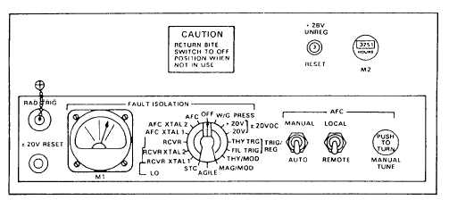
Figure 3-4 shows the controls on the
RT-889/APS-115. There is a fault isolation switch
and meter for checking the operation of the
receiver-transmitter. The AFC section allows the
operator to select the AFC required. There is also an
elapsed time meter and two power reset circuit
breakers.
CAUTION
Return fault isolation switch to the OFF
processing circuits, range mark generating circuit,
position during normal operation. Failure
and BITE circuitry. The receiver processes received
to do so will result in improper operation of
echo pulses, converts them to video, and delivers
the system.
Figure 3-4.-RT-889/APS-115 receiver-transmitter control panel.
3-4