warm-up time, the WARM-UP section will
extinguish, and the STBY section illuminates. This
tells the operator that the system is ready for use.
Press the HV push button now to apply the radar
operating power. When the operating power is
applied, the HV ON section will illuminate. Press the
push button to alternately select HV ON and STBY.
FTC SWITCH.— This switch controls the
receiver’s fast time constant circuitry. With this
switch in the FTC position, the targets displayed have
strong leading edges and attenuated trailing edges.
This improves the display when the target is near a
landmass.
LOAD SWITCH.— This switch controls the
waveguide switch on the ante ma unit. When the
ANT section is illuminated, the RF energy is actually
radiated by the antenna.
In the DUMMY mode of
operation, the RF energy is fed into the dummy load
on the antenna. In this mode, there is no radiation out
of the antenna
CAUTION
Ensure the radar system is in STBY prior
to selecting or deselecting DUMMY Load
to avoid damaging equipment.
PWR SWITCH.— This is the system power
switch. It applies power to the system and starts the
warm-up period.
RCVR GAIN KNOB.— This knob controls the
receiver gain of the system. The operator will adjust
the gain until the radar noise levels are matched
between the forward and aft radars.
VIDEO TEST SWITCH.— This switch will
select the video self-test circuitry in its respective RT
for an overall performance check. If the PULSE push
button is in the LONG position, the display should
show simulated targets 1 nautical mile apart. In the
OFF position, the system is in the normal mode of
operation.
STC DEPTH KNOB.— This knob will vary the
amount of receiver attenuation for close-in targets. It
is used in conjunction with the STC RANGE knob.
STC RANGE KNOB.— This knob varies the
range to which the intensity of target return is
effectively reduced. It will vary the range between 0
and 20 nautical miles. If both the DEPTH and the
RANGE knobs are rotated fully clockwise, close-in
targets could be blanked from the display.
AFC/MAN SWITCH.— This switch selects
either the AFC mode or the manual tuning mode of
operation. In the AFC position, the local oscillator
has the automatic frequency control circuitry
connected to it. With this switch in the MAN
position, the operator can manually tune the local
oscillator. If the system is manually tuned correctly,
there should be no difference in the video in either
position. The system is locked in the fixed-mode of
operation if this switch is in the MAN position,
regardless of the position of the FREQ push button.
MAN TUNE KNOB.— This is the knob the
operator rotates to manually tune the local oscillator
when the AFC/MAN switch is in the MAN position.
FAIL LIGHTS.— There are two lights located on
the control panel to indicate there is a problem with
the system. One is the RT light, and the other is the
APP light. The RT light will illuminate when the
receiver-transmitter BITE circuitry detects a failure in
the RT. The APP light will illuminate when the BITE
circuitry detects a failure in the antenna position
programmer.
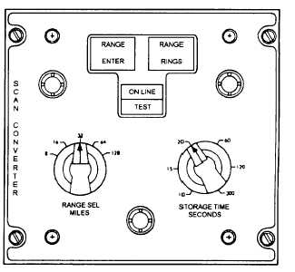
C-7557/ASA-69 Radar Scan Converter
Control
The radar scan converter (fig. 3-6) and associated
components provide the interface between the data
processing system and the APS-115 radar set. It also
Figure 3-6.-C-7557/ASA-69 radar scan converter control
3-6