the antennas will stop at the position established by
the ANT HEADING control.
ANT HEADING KNOB.— This knob provides
control to change the heading of the antenna if the
SCAN switch is in the SECTOR or STOP position.
TILT ALIGN ADJUSTMENT SCREW.— This
control is located on the right side of the control box.
It provides a limited amount of adjustment to align the
tilt axis of the aft antenna to the tilt axis of the forward
antenna due to boresight errors.
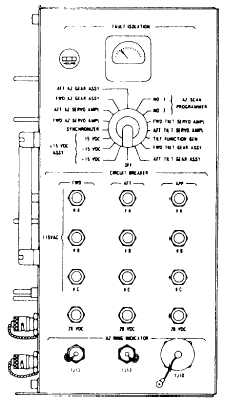
MX-7930/APS-l15 Antenna Position
Programmer (APP)
The antenna position programmer (fig. 3-3) ties
the forward and aft systems together. It generates the
azimuth and tilt drive signals for the antenna drive
motors. The APP also generates timing and
synchronization signals for the receiver-transmitters,
radar interface unit (RIU), and IFF. It combines the
forward and aft video returns into composite signals
for full 360-degree coverage. The APP contains
self-test circuits for automatic fault detection and
Figure 3-3.—MX-7930/APS-115 antenna position
programmer.
isolation, along with logic circuits for proper radar
functions (pulsewidth, PRF, scan speed, and so forth).
On the face of the AFP, there are several operating
devices. These are the circuit breakers, fault isolation
meter, fault isolation switch, and an elapsed time
meter.
CIRCUIT BREAKERS.— There are nine
breakers on the APP. Three are for applying power to
the forward system, three for applying power to the
aft system, and three for applying power to the APP
itself. Each circuit breaker applies one phase of
115 volts ac to its appropriate place.
FAULT ISOLATION METER.— The fault
isolation meter provides GO/NO-GO indications of
the BITE signals selected by the fault isolation
switch.
FAULT ISOLATION SWITCH.— The fault
isolation switch enables the technician to select the
desired BITE signal for display on the fault isolation
meter.
This allows the technician to perform
maintenance on the radar systems. Ensure that this
switch is positioned to OFF for normal mode of
operation.
WARNING
Rotation of the fault isolation switch will
override radome safety interlock switches,
possibly causing personnel injury.
CAUTION
Rotate fault isolation switch on the antenna
position programmer clockwise only.
Equipment damage may otherwise result.
RT-889/APS-115 Receiver-Transmitter
The receiver-transmitter generates the high
energy RF radar transmission pulses, and receives the
reflected target pulses.
A pressurized waveguide
system connects each RT to its respective antenna.
Each RT is controlled by its own control box through
the APP.
There are four major functional subsections in
each receiver-transmitter. These subsections are the
transmitter, the receiver, the waveguide pressurization
system, and the BITE circuitry.
3-3