operator rotates the switch to the particular command
to be changed, changes the corresponding switch, and
then presses the ENTER push button.
NOTE: The ENTER push button
pressed after each selection
COMMAND SELECTION switch
each command to the RIU logic.
must be
on the
to route
There are seven positions on this rotary switch.
Only three of these positions are used. The usable
positions are the HV ON/OFF position, the 400/1600
PRF position, and the RAW RADAR position.
RAW RADAR SWITCH.— This switch allows
the operator to select the type of display presentation.
The options available are either an A-scan, selected
by the A-SCAN position, or a PPI scan, selected by
the PPI position.
PRF SWITCH.— This switch enables the
operator to select either a 1600 or 400 PRF (long or
short pulse mode).
SEARCH RADAR FUNCTIONAL
DESCRIPTION
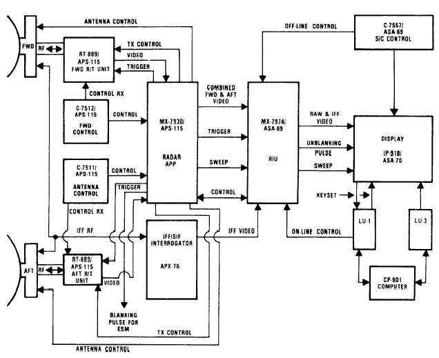
The signal flow block diagram is shown in
figure 3-8. The following section will explain in
more detail the functional signal flow of the various
components.
The forward and aft radar control boxes and the
antenna control box provide mode control to the APP
for execution and distribution throughout the radar
set. The APP processes and coordinates forward and
aft antenna position and scan functions, the
application of power to both sets, and controls
transmit and receive modes of the two RT's.
Figure 3-8.-APS-115 radar signal flow diagram.
3-8