Mode Switch
INDICATOR DISPLAYS
The mode switch is practically self-explanatory.
In the trainer, this switch sets up one of the basic
operating modes available, such as search, bomb
director, or fire control.
Receiver Gain Control
The receiver gain control is one of the most
important controls available to the operator, whether
the pilot in the aircraft or an operator on a trainer.
This control, if not properly adjusted, will prevent the
entire system from operating at peak performance.
Some radar systems include a built-in test function,
which provides a reasonable check of the adjustment
of the receiver gain control. This control is normally
adjusted for best definition of the weakest target
available. There is only one acceptable method for
adjusting this control to obtain peak detection, which
provides maximum range. In each particular radar,
this method is part of the minimum performance test.
Antenna Control (Hand Control)
The hand control of an actual radar installation
allows the operator to select manual search operation
and selection of targets.
Through the use of this
control, the operator may command the radar to
acquire and/or release the target. The 11D13A has
two controls, one for azimuth and one for range.
During automatic search, these controls have two
functions---(1) to position the antenna in elevation
and azimuth, and (2) to select the area to be searched
in relation to the horizon. You can see that these
controls and the receiver gain control are very
important because they will affect target detection
performance.
The hand controls have complete control of the
antenna during manual search, and, in addition, also
control the acquisition symbol to acquire the target.
Auxiliary Controls
Through the use of a scan switch in an operational
radar, the operator may select either full azimuth or
sector scan. The trainer, likewise, incorporates a scan
switch that may be used to select the type of scan
desired. In the trainer, the selections are automatic
sweep at a 6-RPM rate, variable sweep from zero to 6
RPM manually controlled, or sector scan.
A description of the indicator displays (PPI or
B-scope) in the three basic modes of operation and the
submodes of fire control is given in the following
paragraphs.
The indicators are used to monitor
system performance during simulated operation in all
weather conditions.
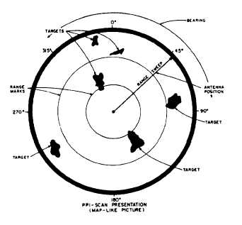
Basic Search
In the basic search mode, information is displayed
on the PPI only. As shown in figure 3-10, the PPI
scan presentation may be a maplike picture of the
earth’s surface being seamed. The range sweep line
rotates in synchronization with the antenna through a
full 360-degree cycle. Targets appear on the face of
the CRT as an intensified light spot. The range of the
target is indicated by its position on the radius of the
range sweep line, and target azimuth position is
indicated by the angle of the sweep line at the time the
target is painted. The top of the scope is 0 degree, and
may indicate dead ahead.
If 1,000-yard marks are selected, the two range
marks shown in the figure are 1,000 yards apart. The
first range mark, which starts from the center of the
scope and moves outward toward the edge of the
scope face, indicates targets from zero to 1,000 yards.
There are two targets shown in figure 3-10 that are
between the 1,000- and 2,000-yard marks. Other
targets are shown at greater ranges and at different
Figure 3-10.-PPI scan presentation basic search.
3-11