Maximum range for tracking is 40,000 yards. At
ranges beyond 40,000 yards, the return echo will be
too weak to maintain lock on. If unlock occurs, the
system is automatically returned to automatic search,
and the cycle of manual track and acquisition must be
repeated to regain target tracking.
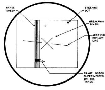
Fire Control (Breakaway)
The final submode of fire control is known as
breakaway. This mode occurs automatically if the
target is tracked to a range that would endanger the
attacking aircraft. During automatic track of a target
that has a decreasing range (attacking aircraft is
closing on the target), the range circle is removed at
the time the range to the target gets to 3,500 yards. In
its place, a large X is displayed, which indicates time
to breakaway from the attack (fig. 3-14). Also at this
time, the steering dot will move to a position on the
scope to indicate the safe direction for the attacking
aircraft to turn to execute a safe breakaway. In the
illustration, minimum range has been reached and the
breakaway X has appeared. The steering dot is
presently positioned to the right and above center.
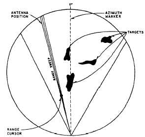
Bomb Director Mode
When the bomb director mode of operation is
selected, information is displayed on the PPI
indicator. In this mode, the antenna automatically
goes to sector scan, scanning a 60-degree arc, 30
degrees to each side of dead ahead. Antenna
elevation is manually controlled. The PPI scope has a
Figure 3-14.-B-scan presentation breakaway indication.
Figure 3-15.-PPI presentation in bomb director mode.
depressed center, which appears as a wedge-shaped
scan on the indicator face, as shown in figure 3-15.
The antenna is positioned in elevation so it will scan
the surface of the earth during a bomb attack. The
B-scope will only display the artificial horizon in the
bomb director mode.
The target tracking range and azimuth strobes
appear on the indicator; they are moved manually so
the marks form a cross hair effect, and are centered
over the target to be tracked. Tracking is maintained
manually in the bomb director mode. The azimuth
and range strobes are controllable from 0 to 80,000
yards, and, in azimuth, 25 degrees to either side of
center.
IFF SYSTEMS
Learning Objective: Recognize components
and operating principles of an IFF
transponder set and an IFF interrogator set.
There are two systems that make up the IFF
system on an S-3 aircraft. These systems are the
AN/APX-76A and the AN/APX-72. Both systems
work in conjunction with the radar set for total and
secure identification.
TRANSPONDER SET AN/APX-72
The transponder set provides Identification
Friend or Foe (IFF) radar replies when challenged by
a valid IFF interrogator.
The IFF transponder
3-15