(±0.25), 73.95 (±0.30), and 94.25 (±0.35) micro-
seconds from the leading edge of the initial framing
pulse. In mode 3/A, one reply pulse train containing
the code 7700 is transmitted, followed by the three
sets of framing pulse pairs with no information
pulses. The location of these framing pulse pairs is
the same as in modes 1 and 2.
Special Position Indicator.— The special
position indicator (SPI) allows the air traffic
controller to differentiate aircraft above or below a
given altitude. This puke is present in the reply pulse
train in mode C when a D4 pulse (18.85 [±0.05]
microseconds from the initial framing pulse) is used.
The SPI pulse is located 24.65 (±0.01) microseconds
from the initial framing pulse. This pulse is
sometimes called the mode C caboose pulse. This
SPI pulse is the initial framing pulse for the second
reply pulse train. The SPI pulse is the same pulse
used in the mode 2 and 3/A IDENT function.
X-Pulse Function.— Special aircraft, such as
drones, are identified by the transmission of the
X-pulse. This pulse (10.15 [±0.05] microseconds
from the initial framing pulse) appears in a normally
unused position.
This pulse is generated when the
IFF transponder control box is modified by grounding
a single external control lead. With this modification,
all replies in modes 1, 2, and 3/A will include this
pulse, along with the normal framing and information
pulses.
SELF-TEST MODE.— When the TEST switches
on the IFF transponder control box are enabled, an
interrogation pulse pair is applied from the test set to
the receiver-transmitter.
Upon receiving these
interrogation pulses, the RT replies to the test set. The
test set then analyzes the replies for bracket-spacing
frequency, power, and antenna circuit VSWR. The
test set will give a GO/NO-GO indication on the
control box. There is a switch for each of the modes
1,2, 3/A, and C.
MONITOR OPERATION.— When the RAD
TEST-OUT-MON switch on the IFF transponder
control box is set to the MON position, the
transponder performance is checked. The test set will
monitor the performance by detecting the replies
generated in response to external interrogation
signals.
If a GO condition is detected, the TEST
indicator on the transponder control box will
illuminate. For a NO-GO condition, the TEST
indicator remains off.
INTERROGATOR SET AFUAPX-76A(V)
The interrogator set is used in conjunction with
the aircraft’s radar set. It provides air-to-air modes 1,
2, 3/A, 4, SIF, and IFF mode 4 challenges. The IFF
interrogator receives a basic trigger from the radar set,
and a delayed radar trigger is returned to the radar
after generation of the IFF interrogator trigger. The
IFF replies are decoded and combined with the
displayed radar return video. The interrogator set
uses receiver side-lobe suppression (RSLS) and
interrogator side-lobe suppression (ISLS). The video
output is developed in the IFF interrogator, and is
applied to the radar set for display.
Interrogator Set Major Components
The interrogator set consists of six major
components. These six are discussed in the following
text.
ANTENNA AS-2719/AP.— The interrogator set
uses an antenna that is hard mounted to the radar set
antenna The IFF portion of the antenna is imbedded
in the upper part of the antenna dish, and consists of
10 IFF elements.
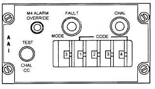
INTERROGATOR SET CONTROL C-7383/
APX-76A(V).— The interrogator control box
(fig. 3-22) provides operating mode selection of the
SIF, or mode 4 code. The control box contains five
thumbwheel switches to select the desired
interrogation mode, or standby, and the desired code.
A momentary two-position toggle switch
(TEST/CHAL CC) allows for loop-testing the IFF, or
to provide correct code challenge. The loop-testing
allows for the interrogation of the onboard
transponder set (AN/APX-72) by the IFF interrogator.
Correct code challenge enables interrogations for
which IFF display pulses are generated if the received
Figure 3-22.-C-7383/APX-76A(V) interrogator control box.
3-20


