SIF reply code is identical to the code switch settings.
There are two indicators (FAULT and CHAL) that
indicate correct operating status of the system. The
mode 4 alarm may be overridden by using the toggle
switch M4 ALARM OVERRIDE.
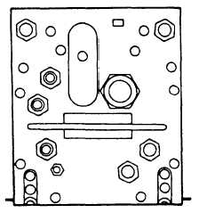
RECEIVER-TRANSMITTER RT-868A/
APX-76A(V).— The receiver-transmitter (fig. 3-23)
takes the mode 1,2, 3/A, or 4 interrogation and ISLS
pulses and modulates a 1030 MHz carrier wave with
them. This is the transmitted signal from the
interrogator set. The transponder reply signal, at the
reply frequency of 1090 MHz, is amplified, detected,
and processed by the receiver section. The reply
video is then sent to the radar set for display on the
various indicators.
There are three fault flags on the front of the RT
that indicate malfunctions in one of the three
functional sections of the receiver-transmitter.
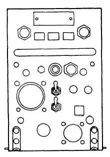
SWITCH-AMPLIFIER SA-1568A/APX-76A
(V).— The switch-amplifier (fig. 3-24) switches the
interrogator’s RF output from the sum antenna
channel to the difference antenna channel for the
duration of the ISLS pulse. During this time, the
output is amplified by 4 to 7 dB. This amplification
provides the required antenna output characteristics.
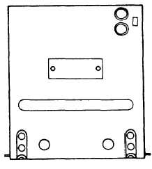
ELECTRONIC SYNCHRONIZER SN-416A/
APX-76A(V).— The synchronizer (fig. 3-25)
generates the initiation and interrogation cycles. The
synchronizer provides a functional link between the
Figure 3-23.-RT-868A/APX-76A(V) receiver-transmitter.
Figure 3-24.-SA-1568A/APX-76A(V) switch-amplifier.
radar trigger generation and the radar modulation
circuits.
COMPUTER KIR-1A/TSEC.— This computer
is used for mode 4 security and decoding for secure
operation.
Interrogator Functional Description
The IFF interrogator challenges and identifies
properly equipped targets on the display groups. It
challenges in modes 1, 2, 3/A, SIF, or mode 4. Target
responses are shown on the display group next to the
target in the form of numbered cues.
MODES 1, 2, AND 3/A TRANSMISSION.—
When the TEST-CHAL CC switch on the interrogator
control box is set to the CHAL CC position, the
interrogation cycle is initiated and lasts for 5 to 10
seconds. The basic radar trigger is applied to the
Figure 3-25.-SN-416A/APX-76A(V) synchronizer.
3-21