transmit a reply when RF interrogation is received
from an IFF interrogator. If the interrogation is valid,
a coded reply is transmitted. This reply is received by
the interrogator and processed for display for aircraft
identification and location. The transponder is
capable of operating in five modes and superimposing
four special signals on the mode replies.
COMPUTER KIT-1A/TSEC.— This computer
allows the IFF transponder to respond to mode 4
interrogations. Mode 4 is a secure mode of operation.
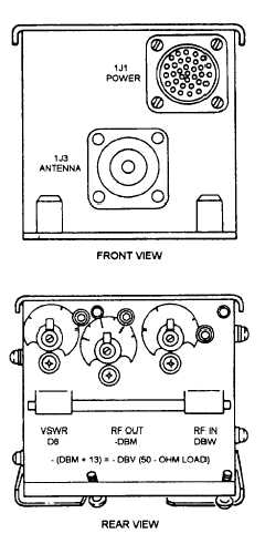
TRANSPONDER TEST SET TS-1843/
APX.— The test set (fig. 3-19) generates properly
coded test signals for the desired mode. These
interrogation signals are then applied to the
transponder. The test set then checks the replies for
frequency, bracket-pulse spacing, power, and antenna
standing-wave ratio. The resulting IFF system check
will provide a GO/NO-GO indication on the IFF
transponder control box.
Transponder Set Functional Description
The IFF transponder control box allows an
automatic IFF capability when the aircraft is
interrogated by a valid interrogation. Special modes
and codes can be manually set on the IFF control box,
receiver-transmitter, and on the computer.
The
control box also initiates the self-test function through
the test set.
RECEIVED SIGNALS.— The interrogator-
transmitted signals are received by the aircraft
through the UHF L-band blade antennas. These
signals are on a frequency of 1030 MHz. The
receiver-transmitter recognizes the signals through
pulsewidth and spacing detection. Modes 1, 2, 3/A,
C, and TEST use two interrogation pulses and one
side-lobe suppression pulse that are 0.8 (±0.1)
microsecond wide. Pulse spacings between the two
interrogation pulses are slightly different, depending
on the mode. These spacings are as follows:
Mode 1:
3.0 (±0.2) microseconds
Mode 2:
5.0 (±0.2) microseconds
Mode 3/A:
8.0 (±0.2) microseconds
Mode C:
21.0 (±0.2) microseconds
TEST:
6.5 (±0.2) microseconds
Figure 3-19.-TS-1843/APX test set.
IFF TRANSPONDER RECOGNITION.—
Recognition of the interrogation mode is done by
passing the first interrogation pulse through a
time-delay circuit and matching this first pulse with
the second pulse position. The delays are of 3, 5, 8,
or 21 microseconds. Mode 4 capability is provided
when the computer is operating in the system. Mode
4 interrogation pulse characteristics consist of four
pulses 0.5 (±0.15) microsecond wide, referenced
from the leading edge of the first pulse in multiples of
2 microseconds. The 4 pulses maybe followed by as
many as 33 additional pulses spaced as close as 2
microseconds. The side lobe suppression pulse is
placed 2 (±0.15) microseconds from the leading edge
of the fourth pulse.
SIDE-LOBE SUPPRESSION.— The side-lobe
suppression pulse allows the transponder to accept the
main lobe and to reject minor lobe signals from the
interrogation stations. This ensures correct operation
of the system.
3-17