CONTROL SERVO FAIL light on the control box. If
the signals are correct, they are fed to the azimuth and
elevation rate compensation modules (E1 and F1) to
develop motor drive signals to slew the receiver head
gimbals maximum CW and up. The rate feedback
signals (gyro rate to E2 and F2 and azimuth
tachometer to mode logic A2 and A3) are fed to servo
BITE (B2). These signals are compared to the signals
(azimuth/elevation rate) from the D/A converter.
Should an error exist, a DCI fault isolate signal is
generated by servo BITE (B2) and fed to mode logic
(A2). Mode logic (A2) sends a known tachometer
signal to the tachometer demodulator. If the
demodulator is bad, a DEMOD fail signal is generated
and sent to B2 that causes a control servo fail output.
If the demodulator is good, but a rate error still exist,
B2 outputs a gimbal fail signal that signifies the
receiver-converter is bad. If the rate comparison
shows no error, a BITE complete signal is generated
by servo BITE (B2) and sent to the power supply-
video converter. If no error has occurred during
BITE, the BITE logic module initiates a system go
signal. This signal is sent to the control box to light
the SYS GO light.
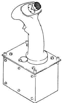
Figure 6-24.-Target tracking sight control.
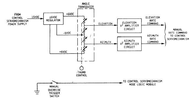
Figure 6-25.-TTSC block diagram.
6-24


