TARGET TRACKING SIGHT CONTROL
As mentioned earlier in this chapter, TTSC is the
manual control used in the manual mode of operation
to position the receiver-converter to the desired LOS.
Figure 6-24 is a drawing of the TTSC. The TTSC
consists of a stationary control stick (A) and the
electronics for producing azimuth and elevation dc
rate command signals. A thumb control (B) is used in
conjunction with an angle transducer to steer the
receiver head. A trigger-type switch (C) is used to
provide manual override.
Figure 6-25 is a simplified block diagram of a
TTSC. A voltage regulator regulates the 15-volt dc
input from the control servomechanism WRA and
provides +6 volts dc and –6 volts dc to an angle
transducer. Adjustment of the thumb control produce
voltage outputs from the elevation and azimuth angle
transducers. These outputs are amplified and sent to
the control servomechanism. Here they are processed
to position the receiver head to the desired LOS.
Should you select the computer tracking mode,
the FWD mode, or the position mode on the control
box, depressing the trigger switch initiates a manual
override command signal. This signal goes to the
mode logic and D/A converter modules. This places
the system in the manual track mode of operation.
INFRARED DETECTING SET CONTROL
(IRDSC)
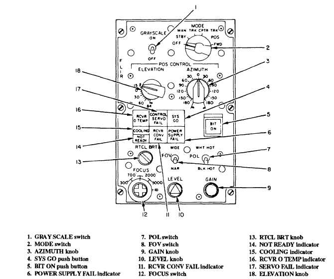
Figure 6-26 is a drawing of an IRDSC/FLIR
control box. Notice that each control has been
Figure 6-26.-IRDSC/FLIR control box.
6-25


