
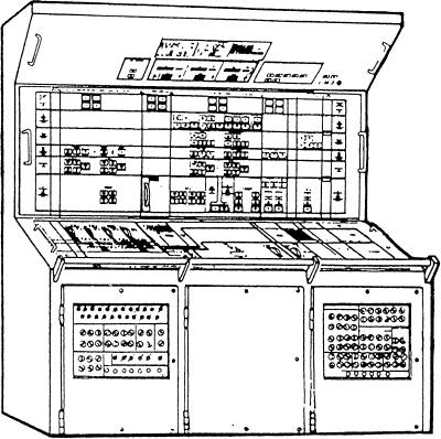
Figure 3-14.--Auxiliary control console.
indicators are arranged on the ACC in a logical manner.
For a detailed description of these systems and the
associated controls and indicators, refer to
This arrangement aids the operator in relating the panel
GSE3/GSM3, Volume 2, NAVEDTRA 10564.
control and monitoring to the location of the auxiliary
systems in the ship.
Parameters considered critical are continuously
displayed on the console for operator monitoring. Those
The following 15 specific auxiliary subsystems
parameters not considered critical are available to the
interface with the ACC:
operator on demand by entering a specific code for the
1. Machinery space ventilation
parameter on a thumbwheel switch assembly. This
assembly is located next to the alphanumeric demand
2. Fuel fall, transfer, and purification
display. In addition to the auxiliary system parameters,
3. Chilled water circulation
all electrical system and propulsion system demand
display parameters can be selected at the ACC.
4. Waste-heat water circulation
The ACC interfaces with the data processor in the
5. Compressed air plants
EPCC to exchange information. The following are three
6. Main engine starting air
of the primary functions performed by this interface.
7 . Potable water
1. Processing of the discrete and analog data to
provide a backup for alarm detection
8. Fill valves
2. Processing of data for output to the demand
9 . Distilling plants
display at the ACC
10. Saltwater service system
3. Data logging through communications with the
11. Drainage system
data processor in the PCC
12. Masker, prairie, and bleed air
Each of these functions is under the control of the
13. Sewage disposal system
electric plant and auxiliary control system software
program. This program is stored in the EPCC data
14. Refrigeration system
processor memory. Data is transferred from the EPCC
15. IC/SM - Summary alarm
to the ACC over digital data lines that connect the digital
3-37