enabled to accomplish an emergency stop at the PCC.
Throttle and Pitch Control System
The emergency stop command causes the circuitry in
The throttle and pitch control system provides
the LOP and FSEE to immediately de-energize the
control of shaft speed and propeller pitch. The control
POWER TURBINE OVERSPEED TRIP switch. This
system can be operated in three modes: local manual
action causes both automatic fuel shutdown valves to
c o n t r o l , remote manual control, and programmed
close and latch. This will shut down the GTE.
control.
EOT Control System
The propulsion control system can be operated in
the manual control mode from the PCC or the LOP. The
programmed control mode is the primary mode of oper-
The EOT control system on the FFG-7 class ship is
ation and is initiated from the PCC or SCC. The relation-
a standard Navy installation. The EOT provides an
ship between the pitch and throttle is automatically
electromechanical communication system between the
scheduled by the PCS in the programmed mode.
bridge and the PCC. The EOT on the PCC is located on
the lower or propulsion control panel and provides
Now that you have read about the control functions
continuous position indication. The EOT also provides
available at the PCC, let's look at those available at the
signals to the discrete multiplexer, which are inputs to
EPCC.
the PCS bell logger program.
EPCC
The EOT is used to relay standard orders from the
bridge to the PCC. When the bridge orders a change of
speed, one of the pointers in the EOT will point to the
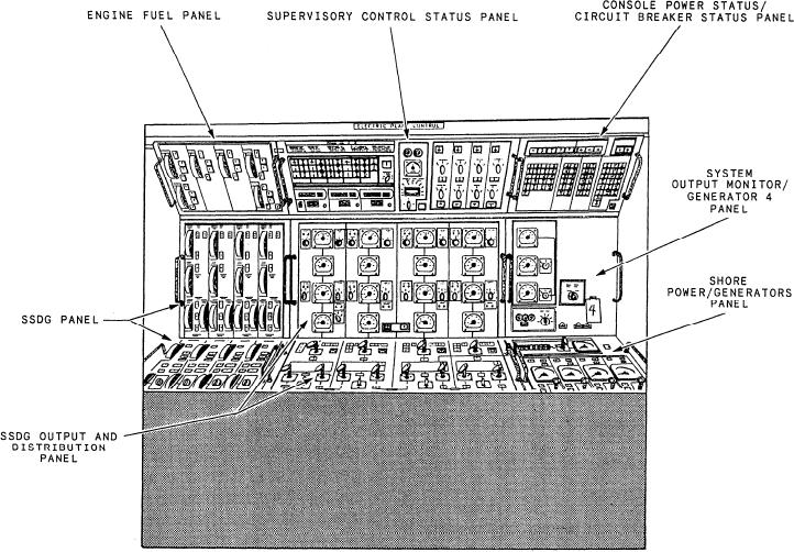
The EPCC contains the controls and indicators that
requested speed. The PCC operator acknowledges the
are used to remotely operate and monitor the ship's
order by moving the other pointer to match the bridge
service power generation, distribution, and related
pointer. This is done by using the knob below the EOT.
support systems. As shown in figure 3-13, each panel
Figure 3-13.--EPCC panel locations.
3-33

