Gearbox Assembly
SSPU Turbine Engine
The external gearbox assembly provides for two of
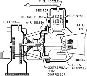
The SSPU turbine engine is composed of four major
the SSPU's mount pads and the mounting area for the
parts: (1) a 2-stage centrifugal-flow compressor, (2) a
SSPU'S power section. The internal gearbox assembly
3-stage axial-flow turbine, (3) an inlet plenum assembly,
contains the reduction gearing that enables the power
and (4) a combustion system. Figure 7-31 is a cutaway
section to drive the supporting accessories and the
view of an SSPU turbine engine showing the relative
loading components at the proper speed. When the
position of each of these components.
power section is operating at 100 percent speed (41,730
The compressor impellers and three turbine wheels
rpm), the unit's gears provide the following output
are locked together by means of curvic couplings. A tie
speeds:
bolt through the center of the wheels makes this
8,000 rpm
assembly a single rotating unit. A floating ring journal
bearing and seal assembly on each end of the shaft
Load compressor
8,000 rpm
support this rotating unit.
Hydraulic pumps
3,600 rpm
Outside air is drawn into the compressor through the
inlet plenum into the combustor where it is mixed with
Lubrication System
fuel. The fuelhir mixture is ignited by the igniter plug
at 10 percent of engine speed. When the unit reaches 95
The SSPU lubrication system provides lubrication
p e r c e n t of engine speed, the ignition system is
for the engine and gearbox assembly, load compressor,
a u t o m a t i c a l l y de-energized because at this point
and generator. It is a full pressure, wet sump system
combustion is self-sustained. The hot gases pass from
consisting of the oil pump assembly, oil falter assembly,
the combustion chamber into the torus assembly. The
oil pressure regulator, and a check valve. The system is
torus assembly directs the hot gases onto the three
also equipped with pressure and temperature switches
turbine wheels. By imparting energy to the turbine
and a temperature sensor for readouts on the PHM
wheels, the hot gases cause them to rotate and provide
indicators. The oil sump is an integral part of the SSPU
shaft power for operation of the compressor, gearbox
assembly. The oil sump has a capacity of 8 gallons and
assembly, and driven equipment. The spent gases are
is equipped with a drain fitting, a dip stick, and a sight
expelled through the tail pipe into the PHM exhaust
glass for monitoring oil quantity. The SSPU lubrication
duct.
system is serviced through a filler cap. The filler cap
should be removed only when the SSPU is shut down.
The oil level should be checked daily.
Fuel System
The SSPU fuel system automatically regulates fuel
f l o w to maintain constant engine speed and safe
operating temperatures under varying conditions of
starting, acceleration, and load application. If the fuel
supply pressure decreases to 4 psig, a LOW FUEL
PRESSURE indicator on the EOS panel will illuminate.
Control Panel
The control panel for each SSPU is located in the
EOS. This panel is divided into three sections, as shown
in figure 7-32. The top section provides switches for
SSPU de-icing and engine wash functions. The center
section provides meters to indicate the operating oil
temperature, oil pressure, exhaust gas temperature, and
percent speed of each SSPU engine. Filter assemblies,
Figure 7-31.--Cutaway view showing main components of an
located on the side of the center panel, are used to filter
SSPU turbine engine.
electromagnetic interference (EMI) generated in the
7-34

