voltage by rotor-mounted silicon diodes and capacitors.
over/underexcitation, and differential phase currents for
The generator is driven at a constant speed through a
both single and parallel operation. In its monitoring
splined shaft that connects the unit to the SSPU gearbox.
function, the GCU activates control circuits to isolate
the faulty output from the ship's electrical distribution
T h e main generator provides its own internal
system.
cooling. Compartment air is drawn in at the generator
outboard end. An external shroud collects the air and
ELECTRICAL DISTRIBUTION SYSTEM
routes it out of the compartment.
The generators each supply separate switchboards
GENERATOR CONTROL UNIT
that serve as the central control points for the PHM's
electrical distribution system. A -b us tie between the
A GCU is installed in each switchboard to monitor
main switchboard busses allows the generators to
t h e corresponding ac generator output. The GCU
supply the ship's systems either individually, in the
m o n i t o r s ac generator output to provide voltage
split-plant mode, or in the parallel mode. There are two
regulation and control and to protect the generator and
switchboards used for power distribution: (1) the main
its electrical load. The GCU provides these functions
deck switchboard and (2) the platform deck
through sensing, time delay, logic, and output control
switchboard.
circuits. These functions are mostly contained on eight
printed circuit boards (PCBs). The PCBs are mounted
Main Deck Switchboard
within a natural convection ventilated enclosure. They
are connected to the switchboard wiring by means of
two multiple pin connectors.
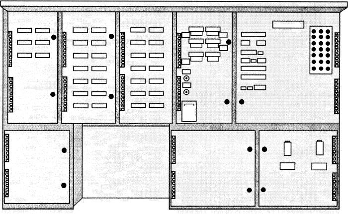
The main deck switchboard (1S) is shown in figure
7-34. The main deck switchboard interfaces electrically
The GCU regulates the generator output voltage by
with the 450-V ac, 400-Hz, 3-phase power output of
controlling the amount of power delivered to the
generator No. 1 and shore power receptacle No. 1.
by monitoring the generator output for
As shown in figure 7-34, the enclosure for this
over/undervoltage, overcurrent, underfrequency,
s w i t c h b o a r d is equipped with hinged doors and
Figure 7-34.--Main deck switchboard.
7-36

