
kVA(180 amperes). It will supply 450-V ac, 3-phase,
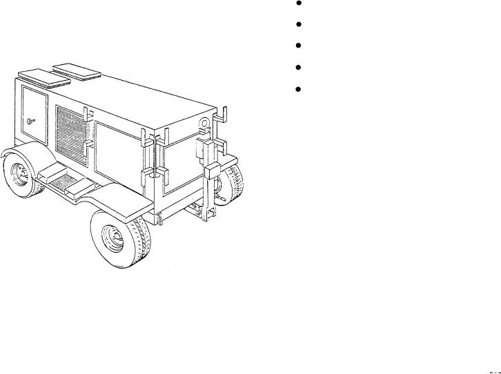
entire enclosure is mounted on a steerable, highway
400-Hz power to the PHM at 125 kW continuous duty.
towable, 4-wheel trailer. (See fig. 7-36.)
The motor generator is a brushless, two-bearing,
TROUBLESHOOTING
PROCEDURES
salient-pole unit. The unit is self-ventilated. The rotating
brushless system consists of the salient-pole motor and
In troubleshooting the PHMs electrical system, you
generator rotor assemblies, fan assembly, rotating
should first use the fault or out-of-tolerance indications
rectifier assembly and exciter armature assembly, all
displayed on the electrical system control panel. You
mounted on a common shaft and dynamically balanced.
should then locate the associated fault directory and
fault trees in the appropriate technical manuals.
The voltage regulator unit is a completely static,
modular unit. It is provided with a plug-in connector for
Use the panel indications and the appropriate
ease of removal and replacement. The regulator contains
guidelines in the technical manuals to analyze the
plug-in circuit modules for 3-phase voltage sensing,
symptoms of the trouble, isolate them to a probable
exciter field control, over/undervoltage monitoring, and
cause, and recommend corrective procedures to return
underfrequency monitoring.
the system to its operational condition. The information
you can derive from the panel indications, the technical
The control panel is hinged for easy access and
manuals, and the electrical power system one-line
provided with a weatherproof shield to prevent direct
diagram should provide you with the information you
rainfall on the panel during operation of the controls or
will need to perform basic fault isolation procedures.
observation of the instruments.
In the preceding sections, you read about the main
The shore power transformer is a 3-phase,
propulsion, power train, control, and electrical systems
single-core, isolating type. It takes power from the
of the PHM. In the following section, we will take a look
power unit input terminals and provides two isolated,
at the auxiliary systems, their components, and the
ungrounded output circuits. The shore power system is
relationship of these systems to the engineering plant.
provided with both input and output circuit breakers,
instruments, and indicators.
AUXILIARY SYSTEMS
T h e mobile electric power unit is capable of
The auxiliary systems of the PHM include the
continuous duty. It can maintain the electrical and
following systems:
physical performance characteristics required for the
Fuel system
PHM under specified input and environmental
conditions. The unit operates on a 480-V ac, 3-phase,
Hydraulic power system
60-Hz power source with a continuous rating of 150
Compressed air system
Seawater system
Bilge drainage system
Let's take a closer look at each of these systems and
how they interface with the engineering plant.
FUEL SYSTEM
The PHM fuel system delivers diesel fuel, marine
(DFM) or JP5 to the hullborne propulsion diesel
engines, to the foilborne propulsion GTE, and to the
SSPUs. The fuel is supplied from dockside or tender
sources through the main deck port or starboard fuel
replenishment fill stations. It is piped to four integral
hull tanks at a rate of 250 gpm without spill or tank
overpressure. From the tanks, the fuel is distributed to
the engines or SSPUs through a cross-feed piping and
Figure 7-36.--Mobile electric power plant.
controls system. The distribution system is serviced by
7-38