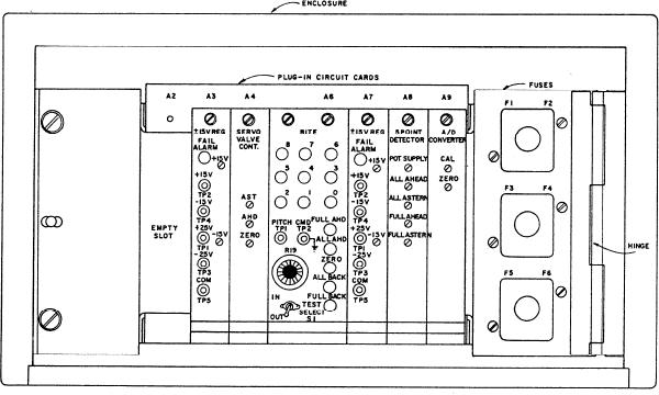
Figure 5-24.--DD-963 CRP eletronics enclosure front panel.
lights that constantly check the five-point level detector
valve controller card also supplies the linear
and A/D converter outputs. The indicating lights are red
potentiometer with +15 volts dc and -15 volts dc.
light emitting diodes (LEDs) mounted in the circuit card
FIVE-POINT LEVEL DETECTOR CIRCUIT
front panel. These lights provide maintenance personnel
C A R D . The five-point level detector causes the
with a local indication of the five-point level detector
five-point indicator light assembly on the PLOE to
output being sent to the PLOE. There are nine A/D bit
display the actual propeller pitch. This is accomplished
lights that check the output of the A/D converter. They
by using the signal from the shaped potentiometer. The
are located on the upper half of the BITE card front
labels on the five indicator lights identify the conditions
panel. Each light monitors one of the nine digital output
F U L L AHEAD PITCH, AHEAD PITCH, ZERO
lines. An illuminated light indicates a digital logic "one,"
PITCH, BACK PITCH, or FULL BACK PITCH. This
which is about 5 volts dc. A darkened light indicates a
display of five indicator lights is also provided on the
digital logic "zero," which is about 0 volt dc These lights
front panel of the built-in test equipment (BITE) circuit
are designed primarily to aid in calibration and testing
card for ease of testing and calibration. The five-point
of the A/D converter.
level detector card also supplies the shaped
potentiometer with +10 volts dc on one end and zero
CG-47 CLASS SYSTEM
volts on the other end.
ANALOG TO DIGITAL (A/D) CONVERTER
The CRP propeller system on the CG-47 class ships
CIRCUIT CARD. The A/D converter output provides
is almost identical to the DD-963 system just discussed.
the digital signals to ECSS for display of the actual
The primary difference is the potentiometer setup on the
propeller pitch. Actual propeller pitch is displayed on
OD box and one card in the CRP electronic enclosure.
the digital demand readouts in the engine rooms and in
The OD box has only one potentiometer that sends
the central control station (CCS). The A/D converter
signals for both indication and control.
receives the shaped potentiometer signal from the
Figure 5-25 shows the CRP electronics enclosure
five-point level detector card. This signal is within the
front panel found on CG-47 class ships. Notice that the
range of 0 to + 10 volts dc The signal is changed by the
A/D converter circuit card in the electronics enclosure
A/D converter circuitry to a nine-bit binary signal. This
has been replaced with a slew rate controller circuit card.
binarn, signal is sent to the ECSS signal conditioning
The purpose of the slew rate controller card is threefold.
enclosure (S/CE).
First, it provides an integrated "burst" signal to the servo
BUILT-IN TEST EQUIPMENT CIRCUIT
valve. This signal is of correct polarity to prevent
CARD. The BITE card contains the local indicating
sticking of the valve and possibly overdriving the actual
5-25

