
cushion (LCAC) vessels. The purpose of CRP/CPP
system is to provide the ahead and astern propulsion
thrust for a ship by changing the pitch of the propeller
blades.
The operation, maintenance, and repair of the CRP,
C P P , and propeller pitch systems are within the
capabilities of ship's personnel. Since these systems
interface electronics with mechanical operations, the
G S E s must work closely with the GSMs when
troubleshooting and repairing these systems.
DD-963/DDG-993 CLASS SYSTEM
The pitch of the CRP propellers is established
electrically through two identical electrohydraulic pitch
control systems. One is located in each main engine
room. Each system has two basic parts or groups of
components. These are the CRP electronics enclosure
and the oil distribution (OD) box-mounted components.
T h e OD box-mounted components consist of the
electrohydraulic servo control valve and two slide-type
potentiometers. Figure 5-23 shows the relationship
between the two basic parts of the system. Refer to
Figure 5-22.--Pictorial view of an ABT.
figure 5-23 as you read the following paragraphs.
The procedures you will use to troubleshoot the
As a good maintenance technician, you should try
t o localize the problem by following the basic
electrohydraulic servo control valve are the same as
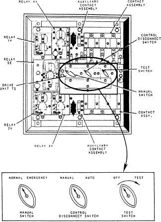
troubleshooting steps. In troubleshooting the ABT, you
those we discussed for troubleshooting solenoids. The
should first make certain that both power sources are
servo valve consists of a two-coil solenoid. Each coil
available to the ABT. If both sources are available, you
has a dc resistance of about 1000 ohms. Check this with
will then have to de-energize both sources of power and
an ohmmeter. The total resistance of the solenoid should
tag the ABT out of service. First check the mechanical
read 500 ohms when you measure it from the two
o p e r a t i o n of the ABT, then make an electrical
conductors that run between the electronic enclosure
examination. After you locate the faulty part, remove it
and the terminal box.
and replace it. Your final step in troubleshooting the
The linear feedback and shaped potentiometers
ABT is testing the effectiveness of your repair.
(LINEAR POT and SHAPED POT in fig. 5-23) are
These troubleshooting steps are general in nature.
mounted side by side on the top of the OD box. Each
Always use the manufacturer's technical manual and the
potentiometer is housed in a rectangular box about 18
appropriate troubleshooting charts whenever you are
inches long, 1 1/2 inches wide, and 1 1/2 inches tall. A
repairing or replacing components of MBTs and ABTs.
shaft that moves the sliding contact extends out of the
forward end of each potentiometer box. A Y-shaped
ELECTROHYDRAULIC CONTROL
yoke connects the ends of the potentiometer that extend
SYSTEMS MAINTENANCE
out the forward end of the OD box. The follow-up rod
provides a mechanical positioning of the potentiometer
An electrohydraulic control system is one that uses
s h a f t s that corresponds to actual propeller pitch
electrical or electronic signals and components to
positions. The follow-up rod also positions a mechanical
control the flow of oil or hydraulic fluids. On gas
pointer along a calibrated scale mounted between the
turbine-powered ships, the most important
potentiometers. Slots in the potentiometer mounting feet
electrohydraulic control system is the controllable
provide for longitudinal position adjustments when you
reversible pitch (CRP) propeller or controllable pitch
propeller (CPP) system. This system is called the
are calibrating the zero pitch feedback and readout
propeller pitch control system on the landing craft, air
signals.
5-23