
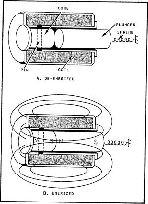
of the plunger in view A when the coil is de-energized.
solenoid-operated valves also contain microswitches to
Compare view A with view B, which shows the plunger
s h o w the valve's position. The console operator
position when the coil is energized. When current flows
depresses a pushbutton to cycle the valve to a new
through the conductor, it produces a magnetic field. The
position. This signal is sent to the solenoid of the valve.
m a g n e t i c flux produced by the coil results in
Depending on the signal received, the solenoid cycles
establishing north and south poles in both the core and
the valve to the requested position. An actuating rod in
the plunger. (See view B.) The plunger is attracted along
the valve rotates or slides, depressing a microswitch.
the lines of force to a position at the center of the coil.
The signal from the microswitch is sent backup to the
As shown in view A of figure 5-20, the de-energized
console, indicating the valve's position.
position of the plunger is partially out of the coil due to
T h e maintenance on solenoid-operated valves
the action of the spring. When voltage is applied, the
includes inspecting, cleaning, testing, and
current through the coil draws the plunger within the
troubleshooting the solenoid and the microswitches.
coil, resulting in mechanical motion. When the coil is
The procedures used to maintain and troubleshoot
de-energized, the plunger returns to its normal position
microswitches were discussed earlier in this chapter. We
because of spring action. The effective strength of the
will now briefly describe the maintenance procedures
magnetic field on the plunger varies according to the
associated with solenoids.
distance between the plunger and the core.
To properly troubleshoot a solenoid, you must first
know how it is constructed and how it works. Figure
Maintenance of Solenoids
5-20 is a cutaway view of a solenoid showing the
solenoid action. A solenoid is an electromagnet formed
If you suspect that a solenoid is not working
by a conductor wound in a series of loops in the shape
properly, your first step in troubleshooting is a good
of a spiral. Inserted within this coil is a soft-iron core
visual inspection. Check the connections for poor
and a movable plunger. The soft-iron core is pinned or
soldering, loose connections, or broken wires. Check the
held in an immovable position. The movable plunger
plunger for cleanliness, binding, mechanical failure, and
(also soft iron) is held away from the core by a spring
improper alignment. Check the mechanism to which the
when the solenoid is de-energized. Notice the position
solenoid is connected (actuates) for proper operation.
Your second step is to check the energizing voltage
with a voltmeter. If the voltage is too low, the result is
less current flowing through the coil and a weak
magnetic field. A weak magnetic field can result in slow
or poor operation. Low voltage could also result in
chatter or no operation at all. If the energizing voltage
is too high, it could damage the solenoid by causing
overheating or arcing. In either case, you should reset
the voltage to the proper value so that further damage or
failure of the solenoid will not result.
Next, check the solenoid coil with an ohmmeter for
opens or shorts, and the proper resistance. If the solenoid
coil is open, current cannot flow through it and the
magnetic field is lost. A short results in fewer turns and
higher current in the coil. The net result of a short is a
weak magnetic field. A high-resistance coil will reduce
coil current and also result in a weak magnetic field. A
weak magnetic field will cause less attraction between
the plunger and the core of the coil. This will result in
improper operation similar to that caused by low
voltage. If the coil is open, shorted, or has changed in
resistance, the solenoid should be replaced.
Finally, you should check the solenoid to determine
Figure 5-20.--Solenoid action.
if the coil is shorted to ground. If you find a short to
5-19