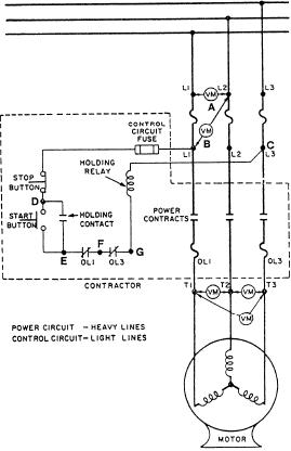
a voltage reading when the START button is
closed.
4. Place the voltmeter probes at points C and F. A
voltage reading with the START button closed
would indicate a good OL1. It also would
indicate one of the following components is
open: OL3, the main coil, the control fuse, or
the connection to L3.
5. Place the voltmeter probes at points C and G.
Close the START button. A no-voltage reading
would indicate that the trouble is located in the
control circuit to OL3.
The following conditions would indicate a faulty
auxiliary contact: (1) The system operates only as long
as the START button is depressed; and (2) when the
button is released, the system shuts down.
When starting a 3-phase motor, if the motor fails to
start and gives a loud hum, you should stop the motor
by pushing the STOP button. These symptoms usually
mean one of the phases to the motor is not energized.
Figure 5-21.--Troubleshooting a 3-phase magnetic controller.
You can assume the control circuit is good. This is
because the main coil has operated and the auxiliary
T1-T2, T2-T3, and T1-T3. The controller is faulty if
contacts are holding the main contactor closed. Look for
there are no voltmeter readings on all three of the
trouble in the power circuit (the main contacts, overload
terminal pairs. You should then proceed to check the
relays, cable, and motor).
main contacts, overloads, and lead connections within
the controller. However, if there is voltage at all three
In the GSE rating you will come across various
terminals, the trouble is either in the motor or the wires
types of control circuits. Some control circuits are more
leading to the motor.
complex than the one shown in figure 5-21, while others
are simpler. The troubleshooting principles we have just
described will work on any type of control circuit. You,
Control Circuit Analysis
however, as the technician, must make certain you have
the correct schematics when you are troubleshooting
any type of electrical controller.
Suppose the overload reset buttons have been reset
and the START button is closed. If the main contacts do
BUS TRANSFER EQUIPMENT
not close, check the control circuit. Your testing
procedure should include the following steps:
Bus transfer equipment is installed at load centers,
1. Check for voltage in the controller at L1, L2, and
distribution panels, or loads that are fed by both normal
L3.
and alternate, or emergency feeders. Bus transfer
2. Place the voltmeter probes at points C and D (fig.
equipment allows you to select either the normal or
5-21). You should have a voltage reading when
alternate source of ship's service power. If an emergency
the STOP button is closed. You should have a
feeder is provided, the bus transfer unit will also allow
no-voltage reading when the STOP button is
you to get power from the emergency distribution
open. These conditions would indicate a good
system.
STOP button and control circuit fuse.
Automatic bus transfer (ABT) equipment allows
3. Next, check the voltage between points C and E.
you to select between two power supplies to obtain
T h e START button is good if you get a
power for the following systems:
no-voltage reading when the START button is
1. Emergency lighting
open. The START button is also good if you get
5-21

