
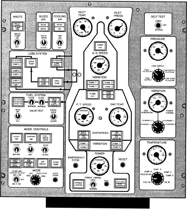
Figure 7-23.--Foi1borne engine control system (FECS) panel at the EOS.
control panel is shown in figure 7-23. Notice that the
the alarm indication becomes normal, the lamp is
2-inch meters are front mounted and clamp held. The
extinguished. Action cutout switches allow the operator
dial faces are white with black markings and the dials
to isolate short-circuited sensors or actuators.
are configured to provide a normal operating pointer
position at the 9 o'clock position. Flow lines are shown
Bulkhead-Mounted Electronics Enclosure
on the fuel, electrical, hydraulic, seawater, freshwater,
and bilge flooding panels and are connected through
The BMEE is located in the EOS. The exterior and
certain annunciators as part of the display. Alarm
interior views of this unit are shown in figure 7-24. The
annunciators flash in conjunction with an audible alarm
BMEE contains the following gas turbine electronics
when an alarm indication is received. When the operator
that interface with the propulsion control system:
presses the flashing annunciator, the audible alarm is
silenced and the visual alarm becomes steady. Anytime
1. Power lever angle (PLA) actuator electronics
7-25