
2 Ready and warning system
✎
Heading hold system
3
✎
4 Foilborne throttle system
✎
Forward and aft hydrofoils
5
✎
6 Bow doors
✎
The FBCS also monitors several critical parameters
of the foilborne system and provides visual (and some
audible) warnings of unsatisfactory conditions. A
self-test feature is available in most sections of the
FBCS. The major systems of the FBCS that allow the
P H M helmsman to monitor and control foilborne
operations are the ACS, the FECS, and the FPCS. In the
following paragraphs, we will take a look at some
examples of how these systems work.
AUTOMATIC CONTROL SYSTEM.-- The ACS
controls the PHM during takeoff, landing, and all
foilborne operations. By automatically positioning the
foilborne control surfaces, such as the forward flap, port
and starboard flaps, and forward strut, in response to
sensed ship motion and manual commands from the
helm, the ACS provides attitude control, stability, and
operation in rough water. The ACS also provides a
self-test capability to allow the operator to perform
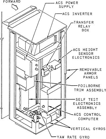
Figure 7-25.--Ship control electronics installation showing ACS.
system operational tests and fault isolation procedures.
The heart of the ACS is the control computer that
receives command inputs and sensor inputs, performs
primary to backup power when a loss of primary power
the necessary logic, and processes the proper control
occurs.
signals to the proper control surfaces. It also receives
Let's look at how this system works. Once the
feedback signals from the position transducer in the
helmsman sets the foil depth level command, the ACS
control surface actuators. Command inputs consist of
m a i n t a i n s the appropriate depth during all ship
heading change (turn) signals from the helm and foil
maneuvers and throughout all sea conditions. As the
depth command signals from the ACS control panel
helmsman rotates the helm for a heading change, the
assembly. Sensor inputs are from attitude sensors
ACS adjusts the flaps and forward strut for a
(gyros), foil depth sensors (height sensors), and heave
coordinated turn. When the helmsman adjusts the
sensors (accelerometers).
foilborne throttle to control the ship's speed, the ACS
The ACS electrical power assembly consists of an
accommodates the resulting hydrodynamic forces that
ACS power supply assembly, an ACS inverter, a dc line
change during the ship's change in speed by adjusting
contactor, an ac line contactor, an isolation transformer,
the ship's pitch angle and the foil's angle of attack to
and blocking diodes. As shown in figure 7-25, these
maintain the required lift. The helmsman can set the
components are all mounted to the top shelf of the ship
ACS MODE switch at the helm station to STRUT
control electronics installation. The ACS power supply
STEERING. This will activate a portion of the ACS and
assembly input is 115 V ac, 400 Hz from either the ACS
t h e forward strut steering circuits, allowing the
inverter, which is powered by +28 V dc (from two dc
helmsman to steer with the forward strut while the craft
panels for redundancy) or from ship's 115 V ac, 400 Hz
is hullborne.
through an isolation transformer. The +28 V dc is the
FOILBORNE
ENGINE
system's primary source with the ship's 115 V ac as the
CONTROL
SYSTEM.-- The FECS
provides for automatic starting
backup source. Circuits within the ACS power supply
assembly monitor the incoming power at the
and stopping of the GTE
and the gearbox auxiliary lube
changeover relay and provide for switching from
oil pump. With the mode
selector switch in the auxiliary
7-27