three panel-mounted gauges, a high-pressure
these to measure the vibration amplitude,
regulator, and a selector valve.
frequency, and phase. These are the three
The third container provides storage for the
vibration characteristics needed to describe and
multimeter and leads, the nitrogen bottle
identify any vibration.
regulator, and the hose assemblies. The nitrogen
bottle is separate and does NOT come with the kit.
Before you calibrate any of the pressure
PRESSURE TRANSDUCER
transducers, be sure the gauges on the calibration
CALIBRATION KIT
units do not require calibrating. For detailed
instructions, refer to Propulsion Gas Turbine
You will use the pressure transducer calibra-
Module LM2.500, Trouble Isolation, volume 2,
tion kit when performing maintenance on the
part 3, S9234-AD-MMO-050/LM2500.
various pressure transducers. The kit consists of
three suitcase type of containers and a dual
diaphragm vacuum pump.
CENTRIFUGE
The absolute pressure calibration unit is in one
container. You will use this unit when calibrating
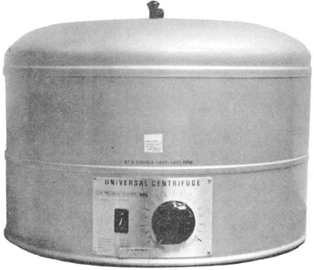
The centrifuge is used to conduct the BS&W
the absolute pressure transducers. The unit has
test on fuel or to separate different liquids and
two panel-mounted gauges, a high-pressure
solids from liquids. The centrifuge (fig. 3-30)
regulator, a vacuum/pressure regulator, and a
consists of a top piece from which four metal tube
selector valve. The three connection ports are for
carriers swing. The carrier holds glass centrifuge
high-pressure supply, regulated pressure out, and
tubes graduated to 100 ml. An electric motor
vacuum source.
rotates the top piece with the tubes. The centrifuge
has an adjustable rheostat to select the speed.
The gauge pressure and differential pressure
To operate the centrifuge, place two tubes with
calibration unit is in another container. Use this
the 100 ml of fuel at opposite ends of the carrier.
unit when you calibrate the gauge pressure and
Then whirl them for 15 minutes at a speed of
differential pressure transducers. The unit has
Figure 3-30.--Centrifuge
3-22

