
three-position lever selects one of three posi-
tions-ENGAGED, DISENGAGED, or SHAFT
LOCKED. Figure 8-9 shows cross-sectional views
of the turning gear mechanism in all three posi-
tions. In the disengaged position, the handle can
be padlocked to a bracket to prevent accidental
movement of the operating lever. Do not attempt
to engage the turning gear while the reduction gear
is operating. Also, do not attempt to operate the
turning gear with the operating lever in the shaft
locked position. Either of these actions will result
in equipment or personnel casualties. With the
turning gear engaged, the gear may be rotated
manually with a wrench. A limit switch assembly
provides electrical signals for TURN GEAR
ENGAGED and SHAFT LOCKED indicators at
the PACC and the PLCC and a disengaged signal
for the ECSS logic. The MRG lube oil header
must have 15 psig of pressure to operate the
turning gear motor.
The drive motor for the turning gear is a
440-volt, 3-phase, 60-hertz electric motor, rated
5 horsepower (hp) at 1,200 rpm. It drives the
turning gear drive shaft through a worm gear. The
turning gear assembly is lubricated by oil sprays
from the MRG lube oil supply header and a self-
contained oil sump.
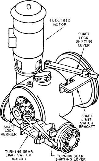
CG CLASS SHIPS.--An electric-motor-
driven, double-reduction turning gear assembly
is mounted on each MRG (fig. 8-10). When
engaged, the turning gear drives through the
upper outboard second-reduction pinion. The
assembly consists of a 7.5-hp-driven motor and
Figure 8-10.--Turning gear assembly (CC class ships).
a double-reduction, spiroid/worm-type speed
reducer. The turning gear assembly is attached to
the MRG through the second-reduction housing
used to engage and disengage the turning gear
flange and the shaft lock ring (stop gear). A
clutch.
flexible coupling attaches the drive motor shaft
The shaft lock shifting lever moves the shaft
to the spiroid pinion in the first-reduction
lock clutch with a shifting yoke. An index plate,
housing. A coupling guard covers the flexible
mounted on the housing, and an indicator plate,
coupling. All bearings in the turning gear
mounted on the worm shaft, make up a turning
assembly are antifriction bearings. Lubrication is
gear shaft lock vernier. This vernier indicates
accomplished by a combination oil immersion and
when shaft lock male clutch teeth are in line with
spray system supplied from the MRG lube oil
the female clutch teeth attached to the turning gear
system at a rate of 3 gpm. The splined gears are
housing. The shaft lock shifting lever locks the
spray-lubricated; the worm gears are lubricated
shaft lock movable male clutch teeth to the
by gear meshes and bearings dipping into a self-
stationary female clutch teeth attached to the
contained reservoir.
turning gear housing. Plates on the gear lock limit
Two shifting levers are provided with the
switch bracket identify two positions of the shaft
turning gear. The shaft lock shifting lever is
lock shifting lever: SHAFT UNLOCKED and
mounted on top of the unit and is used to lock
SHAFT LOCKED. The vernier indicator is used
the shaft adapter to the shaft lock ring. The other
to align the clutch teeth, while an open-end
lever, the turning gear shifting lever, is mounted
wrench is used to rotate the shaft during mating
on the back of the turning gear assembly and is
of the teeth. Limit switches send signals to the
8-19