
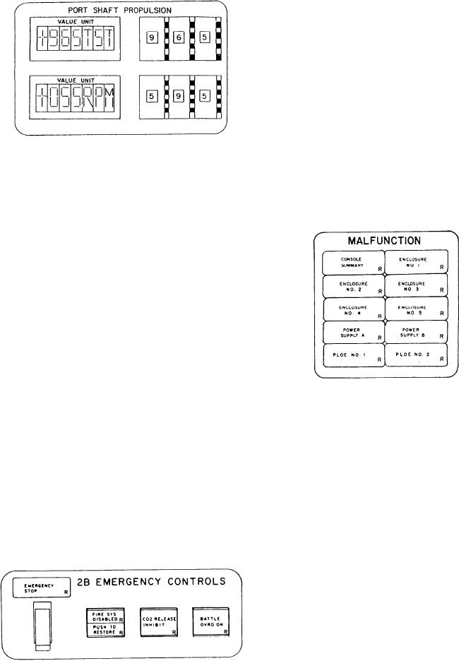
MALFUNCTION Section
has slight physical differences from the DD
console as shown in the following graphic.
This section has 10 alarm indicators used to
monitor summary alarms of the console. The first
alarm indicator, labeled CONSOLE SUMMARY,
illuminates red if an alarm condition has been
detected in the PACC. The next five alarm
indicators across and down are functionally
identical. They are labeled ENCLOSURE NO. 1,
2, 3, 4, and 5, respectively. These alarm indicators
illuminate red if a console malfunction is detected
in one of the five bays of the PACC. The next
two alarm indicators are a pair of functionally
identical indicators labeled POWER SUPPLY A
and POWER SUPPLY B. They illuminate red if
an alarm condition exists in their respective PACC
power supply. The last two alarm indicators are
2B EMERGENCY CONTROLS Section
labeled PLOE NO. 1 and PLOE NO. 2. They
illuminate red if a summary alarm has been
This section is identical on the DD and CG
detected in the respective PLOE electronics.
console. It has an alarm indicator, a guarded
toggle switch, and three push-button control
indicators. The alarm indicator illuminates red
when the PACC operator performs an emergency
stop using the guarded toggle switch directly below
the EMERGENCY STOP status indicator or
when an emergency stop command is generated
by the electronics. The first control indicator is
a split-legend, push-button indicator labeled FIRE
SYS DISABLED/PUSH TO RESTORE. The top
portion of this indicator illuminates red when
the GTM fire detection system is temporarily
disabled. When illuminated, a module fire stop
is prevented from being generated. If the
symptoms causing the casualty are restored prior
to the normal stop timing out, you may restore
the fire system by depressing this switch when the
TEST Section
bottom label illuminates red.
The second push-button control indicator
The TEST section is used for testing all the
labeled CO2 RELEASE INHIBIT is used by the
PACC alarm and status indicators and the siren,
PACC operator to disable the CO2 system while
horn, and bell. It has three momentary-contact
personnel are in the module. It illuminates red
push buttons, a three-position toggle switch, and
when it is depressed at the PACC, PLCC, or when
an eight-position, rotary selector switch. The CG
the CO2 inhibit switch at the module is activated.
console also has a rotary switch to the left of the
The third push-button control indicator, labeled
TEST section which is used to vary the volume
BATTLE OVRD ON, illuminates red when the
of the bell, horn, and siren.
PACC operator depresses it to activate the
battle override electronics.
Under the heading INITIATE are the three
momentary-contact push buttons labeled BELL,
HORN, and SIREN. The PACC operator may
test either audible alarm by depressing the
appropriate push button. On the CG console, the
operator may select a comfortable volume by
depressing the appropriate push button and
rotating the ALARM VOLUME switch to the
acceptable level.
5-28