
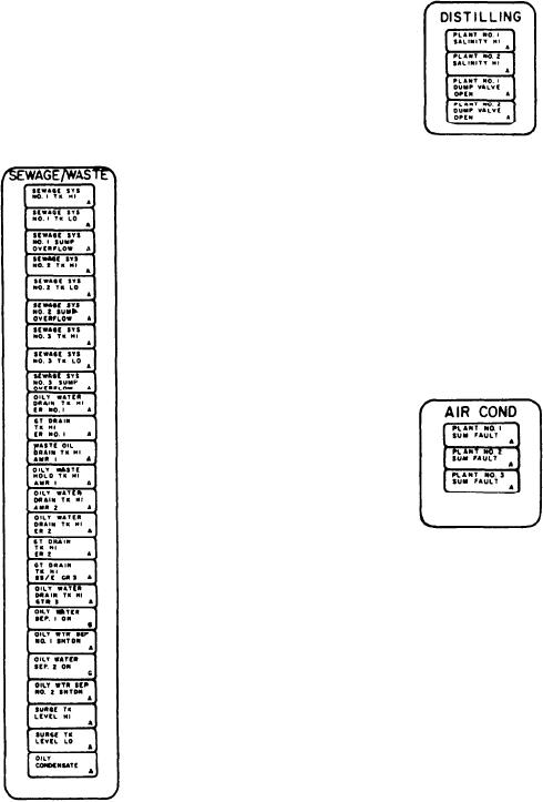
DISTILLING Section
oily water drain tank and gravity drain tank. They
illuminate amber if a high level occurs in their
This section monitors the distilling plants and
respective tank. The eighteenth indicator monitors
has four alarm indicators. The first two alarm
the level of the oily water drain tank in the GTG3
indicators monitor the salinity of distilling plant
enclosure. It illuminates amber if a high level
No. 1 and plant No. 2. They illuminate amber
occurs in the tank.
when a high salinity condition exists at the
respective distilling plant. The next two alarm
The next four indicators are status indicators
indicators monitor the distilling plant No. 1 and
that monitor oily water separators No. 1 and
No. 2 dump valves. They illuminate amber when
No. 2. They illuminate either green to indicate
the respective dump valve has opened due to high
the respective separator is running or amber to
salinity or during system startup.
indicate the respective separator is shut down. The
next two alarm indicators monitor the surge tank
high or low level, respectively. They illuminate
amber if either alarm condition exists in the
respective tank. The last indicator is an alarm
indicator which monitors the condensate of the
oily water separators. It illuminates amber to
indicate an oily effluent is being discharged from
the separators.
AIR COND Section
This section monitors the ship's air con-
ditioning plants and has three alarm indicators
(four on the CG console). These three (four) alarm
indicators monitor summary alarms on A/C
plants Nos. 1, 2, and 3 (and A/C plant No. 4 of
the CG-class ships). The alarm indicators
illuminate amber if a summary alarm is detected
on the respective A/C plant.
SS AIR Section
This section monitors the SSAS and has six
alarm indicators (nine on the CG console) and two
status indicators (three on the CG console). These
alarm indicators and status indicators monitor the
two LP air compressors and receivers (three on
the CG console). The alarm indicators for
each plant monitor for a summary fault (red),
compressor discharge pressure low (red), and
receiver pressure low (red). If a monitored
condition occurs, the appropriate indicator will
illuminate. The status indicators illuminate green
5-24