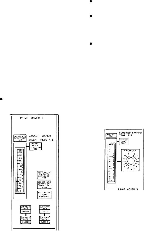
SALT WATER PUMP RUNNING indi-
Jacket Cooling Water System Section
cator indicates the seawater pump is
The jacket cooling water system circulates
running.
fresh water in the diesel engine jacket. The water
OVERBD V OPEN/CLOSED indicator/
is circulated by an engine-driven pump. The top
switch is used to control the seawater
meter, the JACKET WTR OUTLET TEMP,
overboard discharge valve. The upper
provides a continuous display of the jacket water
indicator shows the actual valve position.
temperature. The indicator at the top of the meter
The lower indicator/switch is used to
is the JACKET WATER OUTLET TMP HIGH.
control the valve from the EPCC.
It will illuminate when the jacket water outlet
temperature exceeds the preset limit. The other
SUCTION V OPEN/CLOSED indicator/
indicator for the jacket water system is the
switch is used to control the seawater pump
JACKET WTR EXPANSION TANK LOW
suction valve. The upper indicator shows
LEVEL indicator. It will illuminate when the
the actual valve position. The lower
water level in the expansion tank falls below the
indicator/switch is used to control the
predetermined level.
valve from the EPCC.
Seawater System Section
Exhaust Temperature Section
Each SSDG is provided with a motor-driven
Diesel engine exhaust temperature is measured
seawater circulating pump. The seawater system
by thermocouples mounted in each cylinder
is used to cool the jacket water system. The
exhaust manifold and at the outlet of the exhaust
following alarm indicators and switch/indicators
manifold. The output from the thermocouples are
are for the seawater system:
displayed on the meter labeled EXHAUST
SALT WATER LOW SUPPLY PRES-
TEMP. The switch to the right of the meter is
SURE alarm indicates the pressure in the
labeled CYLINDER. It is used to select which of
seawater system is below the preset limit.
the 16 cylinders will be displayed on the meter.
When any cylinder temperature reaches a
predetermined level, the EXHAUST HIGH
TEMP alarm/indicator will illuminate.
The LAMP TEST push-button switch is located
on the lower right corner of the panel. It is used
to test the indicator lights on the A-7 panel only.
SSDG OUTPUT AND
DISTRIBUTION PANEL (A-8)
The SSDG OUTPUT AND DISTRIBUTION
panel (A-8) is the bottom center panel (fig. 8-20).
8-40

